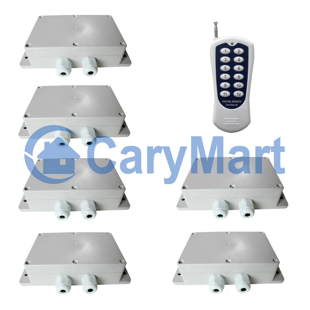
The receiver is designed for one-transmitter-many-receivers system. Use a 12 buttons transmitter to control 6 receivers.

Manual
Package Include:
6 x Receiver: S2PXB-AC220
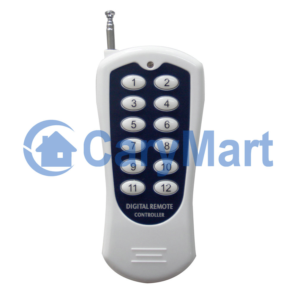
1 x Transmitter: CV-12
1 x User manual
Feature:
Application: It can be used in industry automation, agriculture automation and home automation, such as factory, house, farm, pasture, vehicle, ship, offshore operation, aerial vehicle, field call, etc. It can remote control equipments on land, water and air, such as remote control lights, sirens, locks, motors, fans, winches, blinds, linear actuators, doors, windows, electric solenoid valves, security alarm, business signs and various devices.
Wireless control, easy to install.
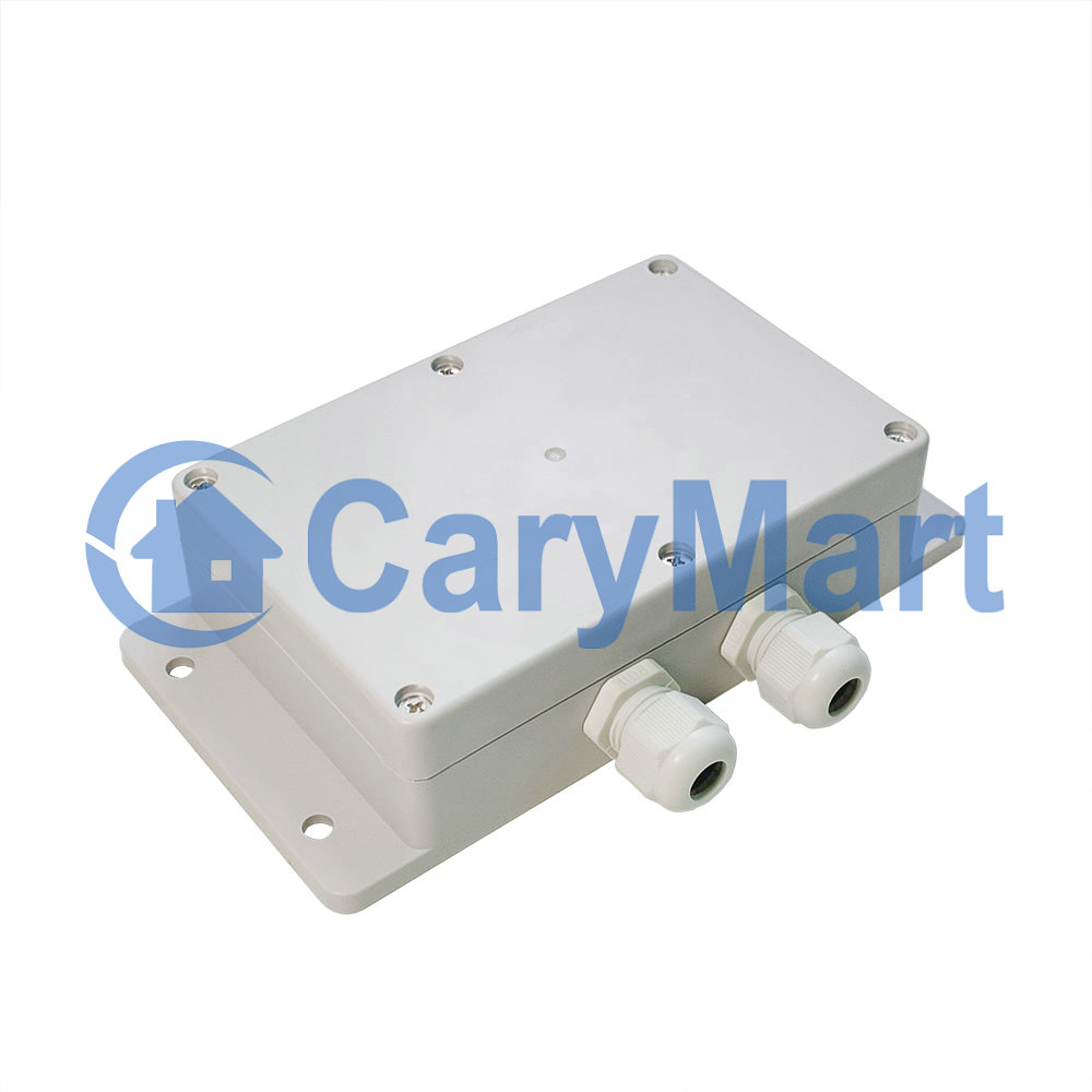
Waterproof: The receiver has waterproof case and waterproof connector, it can be installed outdoors.
Universal input: Support voltage of AC110V (100V~120V), widely used in US, Canada... and voltage of AC220V (200V~240V), used in UK, France...
AC Power Output: It can control AC equipment with voltage 110V / 120V / 220V / 240V AC.
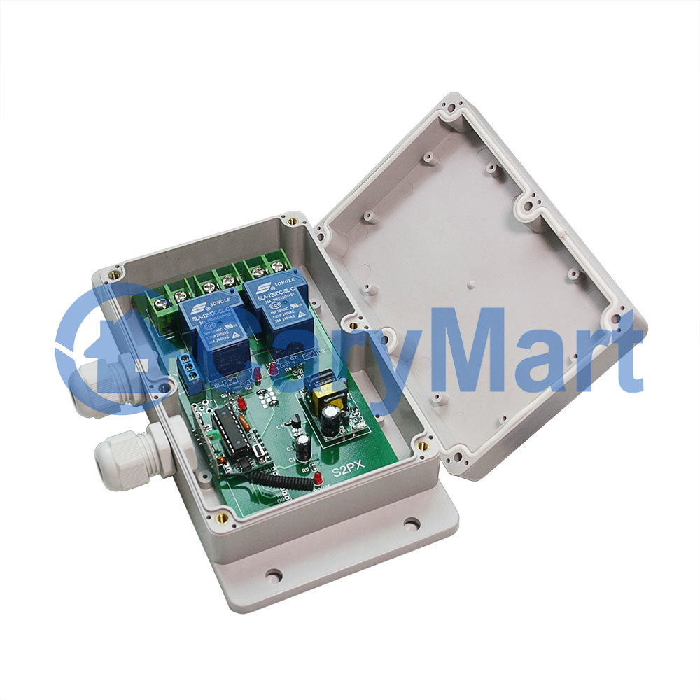
High Power: Each channel can work at maximum current 30A, such as 3000W/110V, 6000W/220V.
With wired control terminals: You can connect sensors, limit switches, manual switches or external devices to control the receiver.
You can turn on/ off the receiver with transmitter (remote control) from any place within a reliable distance.
Wireless RF signal can pass through walls, floors, doors or windows.
With reverse power protection and over current protection.
Reliable control: The receiver only works with the transmitter which use same code.
One/several transmitters can control one/several receivers simultaneously.
You can use two or more units in the same place.
Receiver Parameters:
Model No.: S2PXB-AC220
Power Supply (Operating Voltage): AC100~240V (110V/120V/220V/240V)
Output: AC100~240V (110V/120V/220V/240V)
Working Frequency: 433MHz
Channel: 2 CH
Control Modes: Self-locking, Momentary, Interlocking, Momentary + Self-locking
Static Current: ≤6mA
Maximum Working Current: 30A / each channel
PCB size: 140mm x 73mm x 18mm
Case size: 192mm x 100mm x 45mm
Work with Fixed code transmitters.
Transmitter:
Model No.: CV-12
Channel/Button: 12
Button Symbol: 1, 2, 3, 4, 5, 6, 7, 8, 9, 10, 11, 12
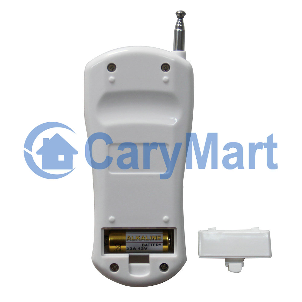
Operating Voltage: 12V (1 x 23A -12V battery, can be used for 12 months)
Operating Current: 15mA
Operating Frequency: 433Mhz
Encoding Chip: PT2262/PT2264/SC2262
Encoding Type: Fixed code by soldering, up to 6561 codes
Transmitting Distance: 500m / 1500ft (theoretically)
Modulation Mode: ASK
Operating Temperature: -20 ° C to +70 ° C
Unit Size: 110mm x 50mm x 18mm
Matching Transmitters:
The receiver can work with different transmitters, such as model CV-12 (500M), or CB-12 (1000M) etc.
Working Range:
With a transmitter (such as CV-12) to form a complete set, the maximum working distance can reach 500M in an open ground.
The maximum working distance is a theoretical data, it shall be operated in an open ground, no barriers, no any interference. But in the practice, it will be hindered by trees, walls or other constructions, and will be interfered by other wireless signals. Therefore, the actual distance may not reach this maximum working distance.
If you want to have a further working range, you can install an external antenna to the receiver, and you also can use a powerful transmitter, such as CB series transmitters.
Usage:
The receiver can be used to control AC 110~240V equipments.
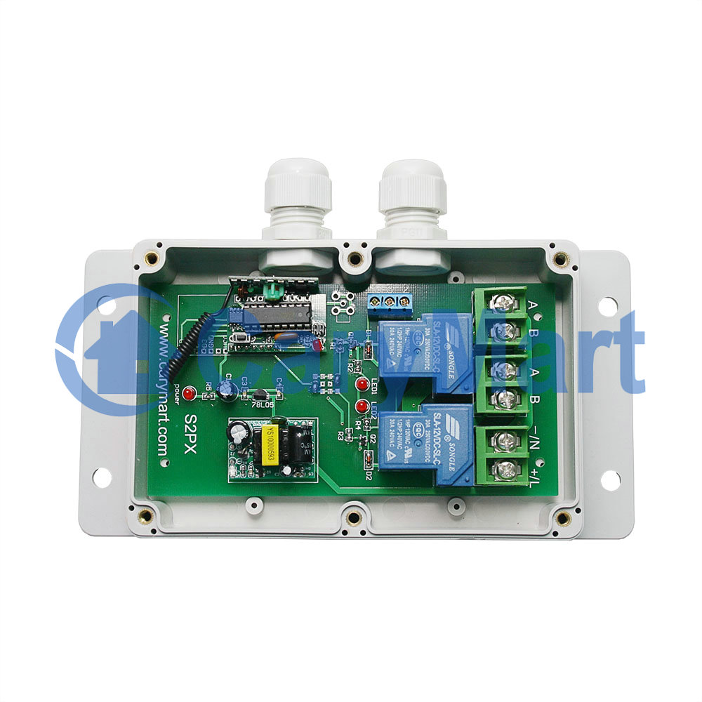
Wiring:
If you want to control an AC 220V lamp, do as following:
1) Connect the live wire of AC power supply to terminal “L / +”, and connect the neutral wire of AC power supply to terminal “N / -”.
2) Connect one side of AC lamp to terminal “A(L)" of OUTPUT, and connect another side of AC lamp to terminal "B(N)" of OUTPUT.
Setting different control modes:
We have set the receiver as Self-locking control mode before delivery. If you want to use other control modes, do as following operation:
Setting control mode Self-locking: Only connect Jumper-2.
Control mode Self-locking (with transmitter CV-12): Press -> On; Press again -> Off.
Press button 1: Terminal A and B of OUT1 of Receiver 1 output AC power, the lamp 1 is on.
Press button 1 again: Terminal A and B of OUT1 of Receiver 1 stop outputting, the lamp 1 is off.
Press button 2: Terminal A and B of OUT2 of Receiver 1 output AC power, the lamp 2 is on.
Press button 2 again: Terminal A and B of OUT2 of Receiver 1 stop outputting, the lamp 2 is off.
…
Press button 11: Terminal A and B of OUT1 of Receiver 6 output AC power, the lamp 11 is on.
Press button 11 again: Terminal A and B of OUT1 of Receiver 6 stop outputting, the lamp 11 is off.
Press button 12: Terminal A and B of OUT2 of Receiver 6 output AC power, the lamp 12 is on.
Press button 12 again: Terminal A and B of OUT2 of Receiver 6 stop outputting, the lamp 12 is off.
Setting control mode Momentary: Only connect Jumper-1.
Control mode Momentary (with transmitter CV-12): Press and hold -> On; Release -> Off.
Press and hold button 1: Terminal A and B of OUT1 of Receiver 1 output AC power, the lamp 1 is on.
Release button 1: Terminal A and B of OUT1 of Receiver 1 stop outputting, the lamp 1 is off.
Press and hold button 2: Terminal A and B of OUT2 of Receiver 1 output AC power, the lamp 2 is on.
Release button 2: Terminal A and B of OUT2 of Receiver 1 stop outputting, the lamp 2 is off.
…
Press and hold button 11: Terminal A and B of OUT1 of Receiver 6 output AC power, the lamp 11 is on.
Release button 11: Terminal A and B of OUT1 of Receiver 6 stop outputting, the lamp 11 is off.
Press and hold button 12: Terminal A and B of OUT2 of Receiver 6 output AC power, the lamp 12 is on.
Release button 12: Terminal A and B of OUT2 of Receiver 6 stop outputting, the lamp 12 is off.
Setting control mode Interlocking: Do not connect Jumper-1 and Jumper-2.
Control mode Interlocking (with transmitter CV-12): Press -> On, other relays Off; Press another button -> Off.
Press button 1: Terminal A and B of OUT1 of Receiver 1 output AC power, the lamp 1 is on.
Terminal A and B of OUT2 of Receiver 1 stop outputting, the lamp 2 is off.
Press button 2: Terminal A and B of OUT2 of Receiver 1 output AC power, the lamp 2 is on.
Terminal A and B of OUT1 of Receiver 1 stop outputting, the lamp 1 is off.
…
Press button 11: Terminal A and B of OUT1 of Receiver 6 output AC power, the lamp 11 is on.
Terminal A and B of OUT2 of Receiver 6 stop outputting, the lamp 12 is off.
Press button 12: Terminal A and B of OUT2 of Receiver 6 output AC power, the lamp 12 is on.
Terminal A and B of OUT1 of Receiver 6 stop outputting, the lamp 11 is off.
Setting control mode Momentary + Self-locking (with transmitter CV-12): connect Jumper-1& Jumper-2
1) Control mode Momentary (Channel 1 of Receiver 1, 2, 3, 4, 5, 6): Press and hold -> On; Release -> Off.
Press and hold button 1: Terminal A and B of OUT1 of Receiver 1 output AC power, the lamp 1 is on.
Release button 1: Terminal A and B of OUT1 of Receiver 1 stop outputting, the lamp 1 is off.
…
Press and hold button 11: Terminal A and B of OUT1 of Receiver 6 output AC power, the lamp 11 is on.
Release button 11: Terminal A and B of OUT1 of Receiver 6 stop outputting, the lamp 11 is off.
2) Control mode Self-locking (Channel 2 of Receiver 1, 2, 3, 4, 5, 6): Press -> On; Press again -> Off.
Press button 2: Terminal A and B of OUT2 of Receiver 1 output AC power, the lamp 2 is on.
Press button 2 again: Terminal A and B of OUT2 of Receiver 1 stop outputting, the lamp 2 is off.
…
Press button 12: Terminal A and B of OUT2 of Receiver 6 output AC power, the lamp 12 is on.
Press button 12 again: Terminal A and B of OUT2 of Receiver 6 stop outputting, the lamp 12 is off.
Wired control terminals:
The receiver has manual control terminals, you can connect external devices, sensors, or manual switches to control the receiver.
1) Signal input:
You can connect external devices (with low level output signal) to manual terminals 1 (Signal +), terminal 2 (Signal +) and terminal 3 (Signal -), then the external device’s output signal can control the receiver.
When the external device outputs low level signal to terminal 1 and 3,Terminal A and B of OUT1 output AC power, the lamp 1 is on.
And when disconnect terminals 1 and 3, Terminal A and B of OUT1 stop outputting, the lamp 1 is off.
When the external device outputs low level signal to terminal 2 and 3,Terminal A and B of OUT2 output AC power, the lamp 2 is on.
And when disconnect terminals 2 and 3, Terminal A and B of OUT2 stop outputting, the lamp 2 is off.
2) The manual switches:
You can connect manual switches to manual terminals 1, 2 and 3, then you can use manual switches to control the receiver.
When connect terminals 1 and 3, Terminal A and B of OUT1 output AC power, the lamp 1 is on.
And when disconnect terminals 1 and 3, Terminal A and B of OUT1 stop outputting, the lamp 1 is off.
When connect terminals 2 and 3, Terminal A and B of OUT2 output AC power, the lamp 2 is on.
And when disconnect terminals 2 and 3, Terminal A and B of OUT2 stop outputting, the lamp 2 is off.