Hi, I'm Tom. Welcome to our shop,
Carymart offers you the premium rf remote control equipment.
We suggest you reading our FAQs before making your decision.
If you have any other question, please contact us.
We will reply you as soon as possible.
Control AC motors of rolling blinds / doors, projection screens, awnings, pumps, winches, conveyors or other appliances and mechanicals with voltage AC 110V/120V/220V/240V.
Universal input: support voltage of AC110V (100V~120V), widely used in US, Canada... and voltage of AC220V (200V~240V), used in UK, France...
You can rotate 2 motors separately in the positive or reversal direction with the transmitter (remote control) from any place within a reliable distance; the wireless RF signal can pass through walls, floors and doors.
With the external telescopic antenna, it can have a further working range.
With characteristics of reverse power protection and over current protection
One/several transmitters can control one/several receivers simultaneously.
If you use two or more receivers in the same place, you can set them with different codes.
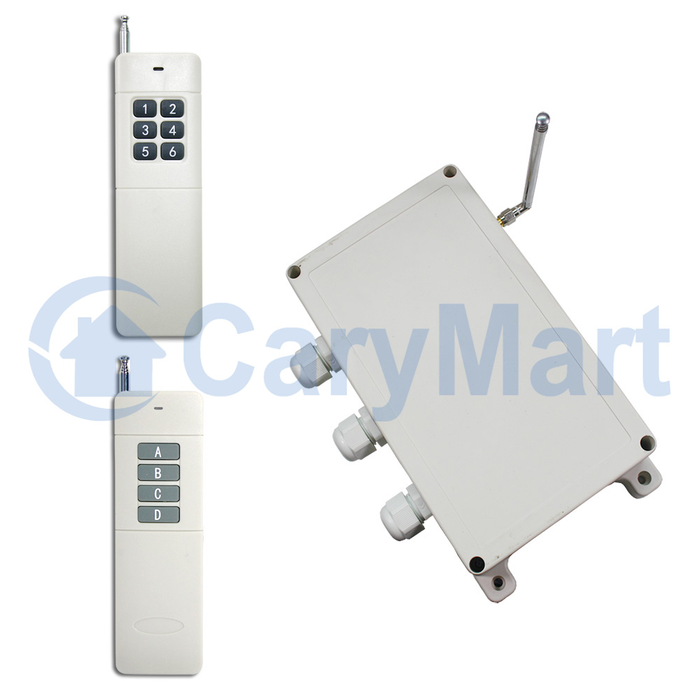
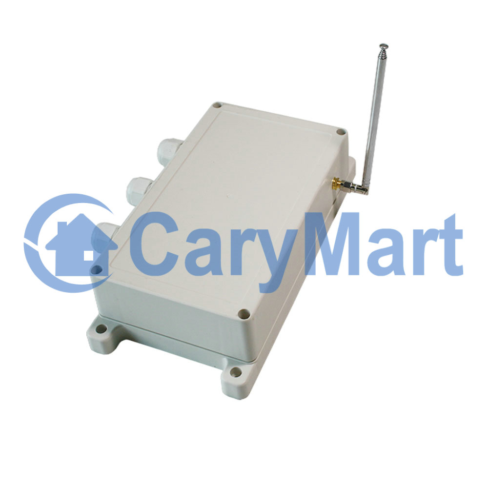
Receiver:
Model No.: S2PF-AC-ANT3
Power Supply (Operating Voltage): AC100~240V (110V/120V/220V/240V)
Transmitting Frequency: 433MHz
Channel: 2 CH
Control Modes: Momentary, Interlocking,
Static Current: ≤6mA
Rated Current: 15A
The Maximum Instantaneous Current of Starting Motor: 30A
Work with Fixed code transmitters or Learning code transmitters.
Coding Setting: By learning
PCB Size: 170mm x 109mm x 18mm
Case Size: 200mm x 120mm x 53mm
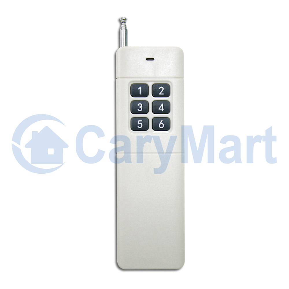
Transmitters Description:
Model No.: 0021027 (CB-6)
Shell Color: Grey
Channel/Button: 6
Button Symbol: 1, 2, 3, 4, 5, 6
Operating Voltage: 9V (1 x 6F22 -9V battery, can be used for 12 months)
Operating Current: 30mA
Operating Frequency: 433Mhz
Encoding Chip: PT2262 / PT2264 / SC2262
Encoding Type: Fixed code by soldering, up to 6561 codes
Length of external telescopic antenna: 108mm / 445mm (stretch)
External telescopic antenna use SMA connector.
If you stretches the external telescopic antenna, it can have a further working range, which is twice as much as it used to be.
The working range:
With a transmitter (such as CV-6-2) to form a complete set, the distance can reach 500m. The distance of 500m is a theoretical data, it shall be operated in an open ground, no barriers, no any interference. But in the practice, it will be hindered by trees, walls or other constructions, and will be exposed to some interference by other signals. Therefore, the actual distance may or may not reach 500m.
If you want to have a further working range, you can install a magnetic sucker antenna (model 0020910).
Usage:
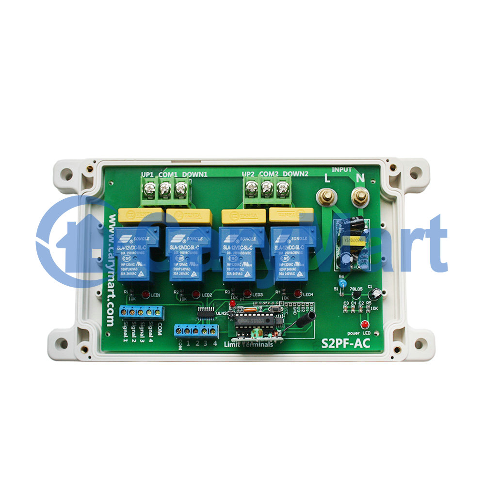
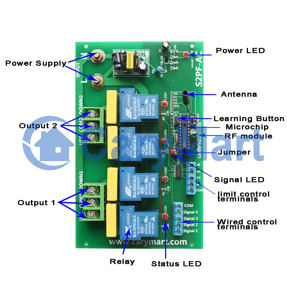
Connect live wire to terminal “L” and neutral wire to terminal “N”. Then connect motor 1 to terminals “UP1”, “COMMOM1” and “DOWN1”, connect motor 2 to terminals “UP2”, “COMMOM2” and “DOWN2”. You can exchange “UP” and “DOWN” wires of motor to change the rotating direction of motor.
Setting control mode Momentary: (working with the transmitter like CV-4-2):
Press and hold button ▲ on the left: motor 1 rotates in positive direction
Release button ▲ on the left: motor 1 stops
Press and hold button▼ on the left: motor 1 rotates in reversal direction
Release button ▼ on the left: motor 1 stops
Press and hold button ▲ on the right: motor 2 rotates in positive direction
Release button▲ on the right: motor 2 stops
Press and hold button▼ on the right: motor 2 rotates in reversal direction
Release button ▼ on the right: motor 2 stops
Setting control mode Interlocking: (working with the transmitter like CV-6-2):
Press button ▲ on the left: motor 1 rotates in positive direction
Press button ▼ on the left: motor 1 rotates in reversal direction
Press button ■ on the left: motor 1 stops
Press button ▲ on the right: motor 2 rotates in positive direction
Press button ▼ on the right: motor 2 rotates in reversal direction
Press button ■ on the right: motor 2 stops
The limit switch:
You can connect a limit switch to the receiver to stop the motor when the limit is tripped. Or you can also connect a manual switch or a sensor to stop the motor.
When motor 1 rotates forward, if connect two limit terminals COM and 1, relay 1 stop working, the motor will stop automatically.
When motor 1 rotates reversal, if connect two limit terminals COM and 2, relay 2 stop working, the motor will stop automatically.
When motor 2 rotates forward, if connect two limit terminals COM and 3, relay 3 stop working, the motor will stop automatically.
When motor 2 rotates reversal, if connect two limit terminals COM and 4, relay 4 stop working, the motor will stop automatically.
Input control terminals:
The receiver has four input control terminals, you can connect external devices, sensors, or manual switches to these terminals to control the outputs of receiver.
1) Signal input:
You can connect external devices (with low level output signal) to terminals “COM”, “Signal 1”, “Signal 2”, “Signal 3”, “Signal 4”, the external device’s output signal can control receiver’s four outputs.
When the external device outputs low level signal to terminal “COM” and “Signal 1“, Relay1 works, the motor 1 rotates forward.
When the external device outputs low level signal to terminal “COM” and “Signal 2“, Relay2 works, the motor 1 rotates reversal
When the external device outputs low level signal to terminal “COM” and “Signal 3“, Relay3 works, the motor 2 rotates forward.
When the external device outputs low level signal to terminal “COM” and “Signal 4“, Relay4 works, the motor 2 rotates reversal
2) The manual switches:
You can connect four manual switches to terminals “COM”, “Signal 1”, “Signal 2”, “Signal 3”, “Signal 4”, then you can use these manual switches to control the outputs of receiver.
When connect terminals “Signal 1” and “Com”, Relay1 works. And when disconnect “Signal 1” and “Com”, Relay1 stops outputting, the motor 1 will stop automatically.
When connect terminals “Signal 2” and “Com”, Relay2 works. And when disconnect “Signal 2” and “Com”, Realy2 stops outputting, the motor 1 will stop automatically.
When connect terminals “Signal 3” and “Com”, Realy3 works. And when disconnect “Signal 3” and “Com”, Realy3 stops outputting, the motor 2 will stop automatically.
When connect terminals “Signal 4” and “Com”, Realy4 works. And when disconnect “Signal 4” and “Com”, Realy4 stops outputting, the motor 2 will stop automatically.