Application:
This receiver is a wireless controller for AC motor, it and the transmitter
form a wireless transmitter receiver system. If you connect a AC motor to
this receiver, you can operate the motor to rotate in positive or reversal
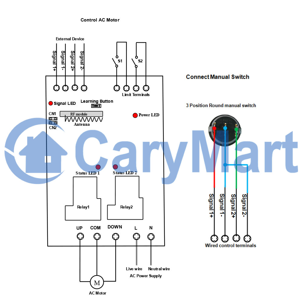
direction by the remote control. You can connect two limit switches to the
receiver and use them to stop the motor. It can be used in rolling blinds,
rolling doors, projection screens, awnings, pumps, winches, conveyors or
other appliances and equipment with AC motors.
Feature:
Wireless control, easy to install.
Suitable for AC motors.
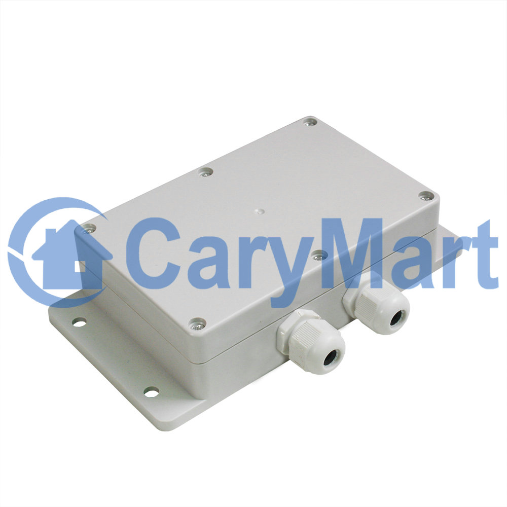
Waterproof: The receiver has a waterproof case and waterproof connector, it
can be installed outdoors.
Universal input: Support 110V AC (110V~120V) used in US, Canada, etc, and
220V AC (220V~240V) used in Germany, UK, France, etc.
High Power: It can work at maximum current 30A.
With limit control terminals: You can connect sensors, limit switches or
external devices to stop the motor or the linear actuator.
You can use the transmitter / remote to control the receiver from any place
within a reliable working distance.
The wireless RF signal from the transmitter can pass through walls, floors,
doors or windows, but it will lose some operating range.
The receiver has reverse power protection and over current protection built
in.
The receiver only works with the selected transmitter which is matched to
the receiver.
One or more transmitters / remotes can control one or several receivers
simultaneously.
Two or more receivers may be used in the same area.
Receiver Parameters:
Model: S1PFC-AC
Operating Voltage: 110~240V AC (110V/120V/220V/240V), but does not work on
US 220V motors.
Working Frequency: 433.92 MHz
Quiescent Current: ≤6mA
Channel: 1 CH, can work with 1 AC motor
Output Type: 110~240V AC (110V/120V/220V/240V)
Maximum Working Current: 30A / each channel, so motor's maximum starting
current cannot exceed 30A.
Suitable Wires for Connecting Terminals: 22-12 AWG
2 Selectable Modes: Momentary, Interlocking
Operating Temperature: -20 °C ~ +70 °C
PCB Size: 140 x 73 x 18 mm (5.5 x 2.9x 0.7 inches)
Case Size: 192 x 100 x 45 mm (7.5 x 3.9 x 1.8 inches)
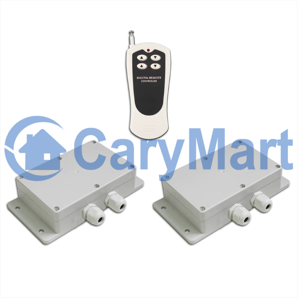
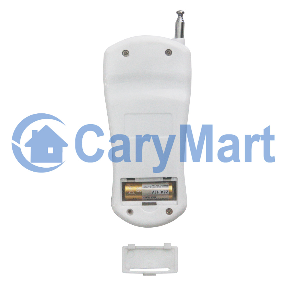
Transmitter:
Model: 0021052 (CV-6-2)
Channel/Button: 6
Button Symbol: Two▲, Two▼, Two■
Operating Voltage: 12V (1 x 23A -12V battery, can be used for 12 months)
Operating Current: 15mA
Operating Frequency: 433Mhz
Encoding Chip: PT2262/PT2264/SC2262
Encoding Type: Fixed code by soldering, up to 6561 codes
Transmitting Distance: 500m / 1500ft (theoretically)
Modulation Mode: ASK
Operating Temperature: -20 ° C to +70 ° C
Unit Size: 110 x 50 x 18 mm
Working Range:
The receiver and transmitter (such as CV-6-2) form a complete set, the
maximum working distance may reach 500 meters in an open area.
The maximum working distance is based on theoretical data without obstacles
and any RF interference. In practice, it will be hindered by trees, walls,
or other construction, and will be interfered with by other wireless
signals. Therefore, the actual working distance may not reach this maximum
distance.
The receiver equipped with an external antenna has a larger working range
than the receiver equipped with an internal antenna.
Usage:
The receiver can be used to control AC 110~240V (110V/120V/220V/240V) motor.
Note: It does not work on US 220V power supply or 220V motors.
Wiring:
If you want to control an AC 120V motor, do as following:
1) Connect the live wire of AC power supply to terminal L, and connect the
neutral wire of AC power supply to terminal N.
2) Connect the forward wire of the AC motor to the terminal UP, connect
the reverse wire of the AC motor to the terminal DOWN, and connect the
neutral wire of the AC motor to the terminal COM.
Setting different working modes:
The receiver will be set in Interlocking mode before leaving the factory, if
you require momentary mode, please follow the following steps.
1) Setting Interlocking mode: Press the learning button in the receiver 4
times, signal LED continuously flashes 4 times and then goes off.
The operation by the transmitter, such as CV-6-2:
Press the button ▲ on the first column of the transmitter: Motor 1 in the
receiver 1 rotates in positive direction.
Press the button ▼ on the first column of the transmitter: Motor 1 in the
receiver 1 rotates in reversal direction.
Press the button ■ on the first column of the transmitter: Motor 1 in the
receiver 1 stops.
Press the button ▲ on the second column of the transmitter: Motor 2 in the
receiver 2 rotates in positive direction.
Press the button ▼ on the second column of the transmitter: Motor 2 in the
receiver 2 rotates in reversal direction.
Press the button ■ on the second column of the transmitter: Motor 2 in the
receiver 2 stops.
2) Setting Momentary mode: Press the learning button in the receiver 2
times, signal LED continuously flashes 2 times and then goes off.
The operation by the transmitter, such as CV-6-2:
Press and hold the button ▲ on the first column of the transmitter: Motor 1 in
the receiver 1 rotates in positive direction.
Release the button ▲: Motor in the receiver 1 stops.
Press and hold the button ▼ on the first column of the transmitter: Motor 1 in
the receiver 1 rotates in reversal direction.
Release the button ▼: Motor in the receiver 1 stops.
Press and hold the button ▲ on the second column of the transmitter: Motor
2 in the receiver 2 rotates in positive direction.
Release the button ▲: Motor in the receiver 2 stops.
Press and hold the button ▼ on the second column of the transmitter: Motor 2
in the receiver 2 rotates in reversal direction.
Release the button ▼: Motor in the receiver 2 stops.
Limit control terminals:
The receiver has limit control terminals, and you can connect external
devices (with normally closed contact), such as sensors, limit switches to
limit terminals, then use them to stop the motor.
For example, you can connect a normally closed limit switch to the two
terminals of S1, and connect another normally closed limit switch to the two
terminals of S2.
When the motor rotates in positive direction, if disconnect two terminals of
S1, the motor will stop automatically.
When the motor rotates in reversal direction, if disconnect two terminals of
S1, the motor will stop automatically.
How to pair the transmitter to the receiver:
Notice: We have paired the transmitter to the receiver before leaving the
factory. If you want to pair more transmitters, please follow the following
steps.
You can freely pair any column of three buttons on the transmitter with the
receiver you want to control.
1) Select the receiver to be controlled and press the learning button in the
receiver once, the signal LED on the receiver flashes once and then stays
on, it means the receiver enters the learning state.
2) Select the three buttons in the column you want to use on the
transmitter, press the first button, if the signal LED flashes for 1 time,
it means that the first button pairing is successful, press the second
button, if the signal LED flashes for 1 time, it means that the second
button pairing is successful, then press the third button, if the signal LED
flashes for 1 time, it means that the third button pairing is successful.
3) Press the learning button in the receiver again for 1-2 seconds, signal
LED turns off, this indicates that the receiver exits the learning status.
4) The receiver can learn several transmitters with different codes.
How to delete all transmitters codes stored in the receiver:
Notice: We have paired the transmitter to the receiver, if you don’t want
the receiver to work with the transmitter, you can delete all transmitters
codes stored in the receiver.
Operation: Press the learning button in the receiver 10 times and then
release the learning button, signal LED flashes 10 times quickly and then
goes off, this indicates that all stored codes have been deleted
successfully.
Package Include:
2 x Receiver: S1PFC-AC
1 x Transmitter: CV-6-2
1 x User manual