Hi, I'm Tom. Welcome to our shop,
Carymart offers you the premium rf remote control equipment.
We suggest you reading our FAQs before making your decision.
If you have any other question, please contact us.
We will reply you as soon as possible.
Application:
It can be used in industry automation, agriculture automation
and home automation, such as factory, house, farm, pasture, vehicle, ship,
offshore operation, aerial vehicle, field call, etc. It can remote control
equipments on land, water and air, such as remote control lights, sirens,
locks, motors, fans, winches, blinds, linear actuators, doors, windows,
electric solenoid valves, security alarm, business signs and various
devices.
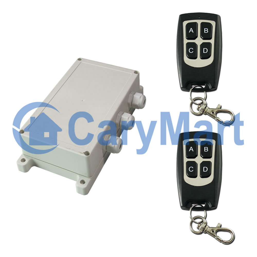
Feature:
Wireless control, easy to install
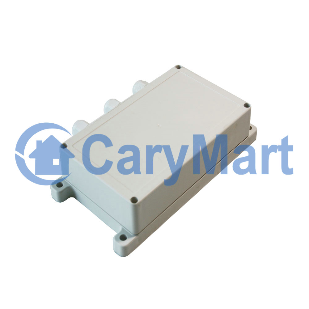
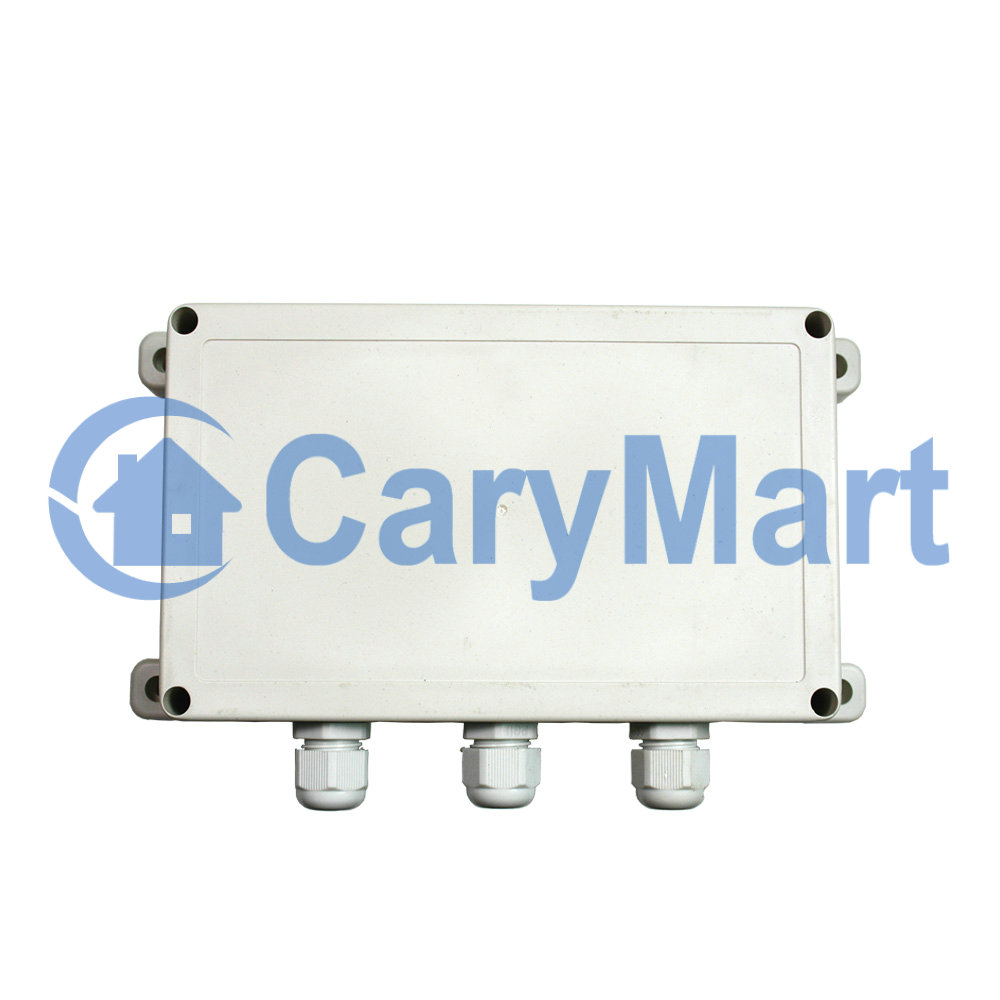
Waterproof case with waterproof connectors.
High power, each output can work at maximum 30A current.
DC power output, can be used in home automation, such as security system,
remote control lights, motors, doors / locks / windows / blinds / cars, and
various equipment.
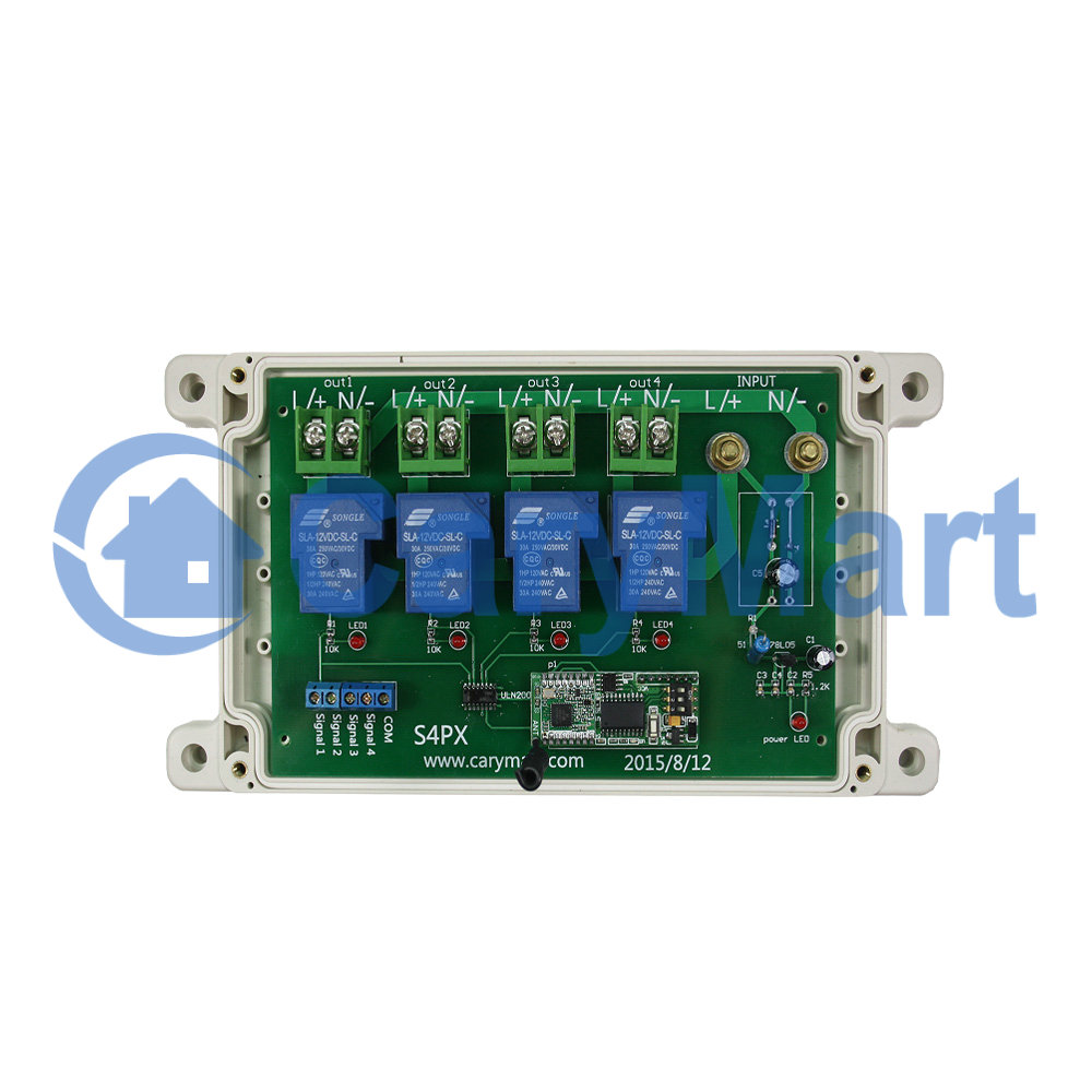
The receiver has four input control terminals, you can connect external
devices, sensors, or manual switches to these terminals to control the
outputs of receiver.
It also can be used in agriculture and industry automation, such as long
range and high power remote control devices.
You can turn on/off the receiver with transmitter (remote control) from any
place within a reliable distance; the wireless RF signal can pass through
walls, floors and doors.
With characteristics of reverse power protection and over current protection
Use an 8-bit microprocessor designed and developed with low-power and
high-speed CMOS technology.
Reliable control: The transmitter (Encoding) and the receiver (Decoding) use
an 8-bit code.
One/several transmitters can control one/several receivers simultaneously.
If you use two or more units in the same place, you can set them with
different codes.
Receiver parameters:
Model: S4PX-DC06-ANT3 / S4PX-DC09-ANT3 / S4PX-DC12-ANT3 / S4PX-DC24-ANT3
Power Supply (Operating Voltage): DC6V (S4PX-DC06), DC9V±1V (S4PX-DC09),
DC12V±1V (S4PX-DC12), DC24V±2V (S4PX-DC24)
Output: DC6V (S4PX-DC06), DC9V (S4PX-DC09), DC12V (S4PX-DC12), DC24V
(S4PX-DC24)
Working Frequency: 433.92MHz
Channel: 4 CH
Control Modes: Self-locking, Momentary, Interlocking, Momentary +
Self-locking
Maximum Working Current: 30A / each channel
Static Current: ≤6mA
Operating Temperature: -20 ° C to +70 ° C
Wire range for the terminals: 22-12AWG
PCB size: 170 x 109 x 18 mm (6.7 x 4.3 x 0.7 inches)
Case size: 200 x 120 x 53 mm (7.8 x 4.7 x 2.1 inches)
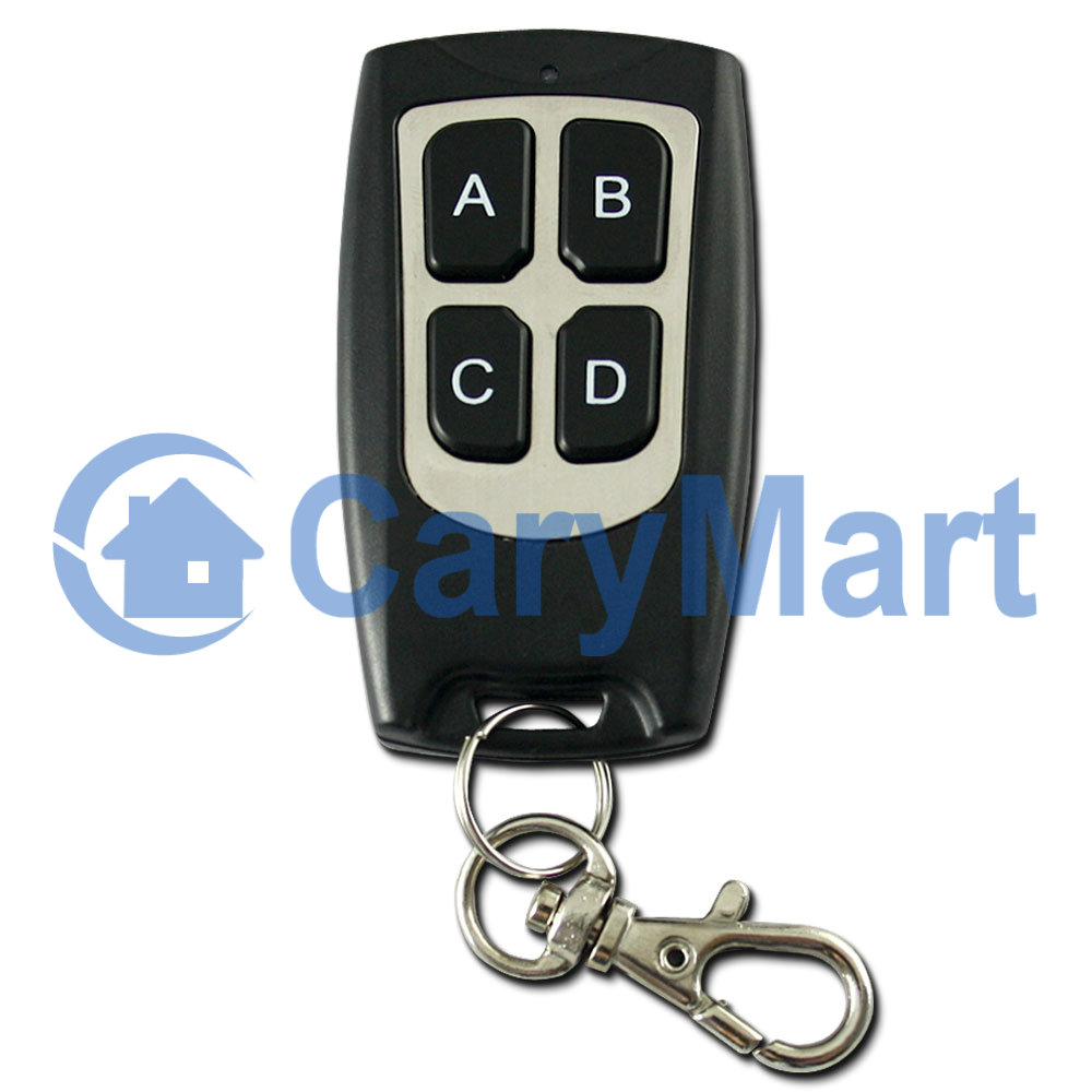
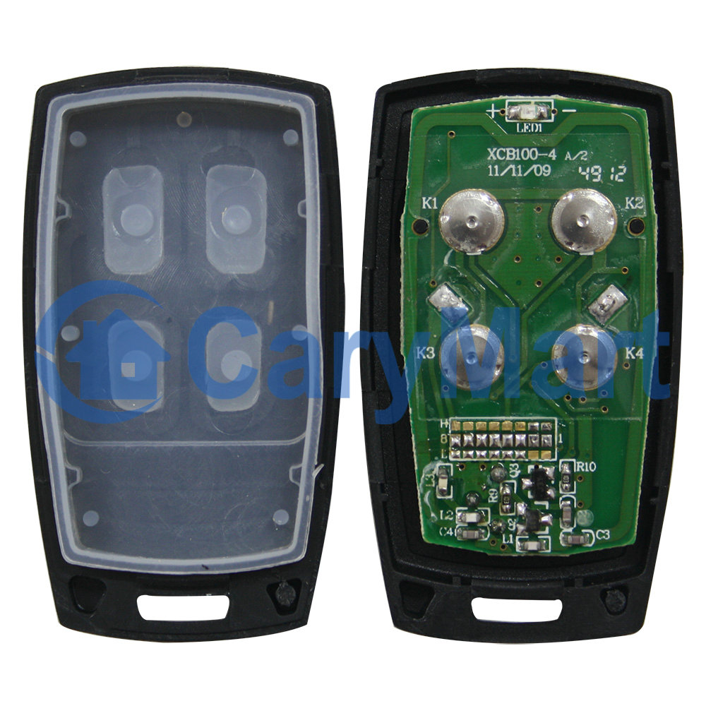
Transmitter Parameters:
Model: 0021003 (C-4)
With Sliding Cover: Slide up when it doesn’t work (to protect the button).
Slide down the button will appear.
Shell Color: White / Wood color
Channel/Button: 4
Button Symbol: 1, 2, 3, 4
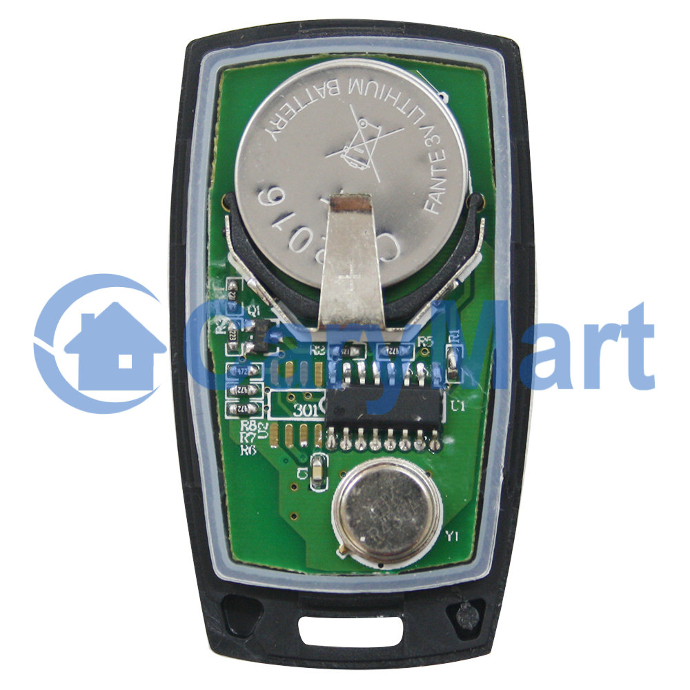
Operating Voltage: 12V (1 x 23A -12V battery, can be used for 12 months)
Operating Current: 6mA
Operating Frequency: 433Mhz
Encoding Chip: PT2262 / PT2264 / SC2262
Encoding Type: Fixed code by soldering, up to 6561 codes
Transmitting Distance: 100m / 300ft (theoretically)
Modulation Mode: ASK
Operating Temperature: -20 ° C to +70 ° C
Unit Size: 58 x 39 x 16 mm
External Telescopic Antenna ANT3 For Receiver:
Length of external telescopic antenna: 108mm / 445mm (stretch)
With SMA connector.
If you stretches the external telescopic antenna, it can have a further
working range.
Matching Transmitters:
The receiver can work with different transmitters, such as model
C-4
(100M),
CWB-4
(50M, waterproof),
CP-4
/
CV-4
(500M), or
CB-4
(1000M) etc.
You also can use four transmitters with one button to work with this
receiver, and each transmitter will control receiver’s a channel. Such as
model
C-1
(100m),
CWB-1
(50m, waterproof),
CP-1
(500M) and
CB-1
(1000M)
etc...
Working Range:
With a transmitter (such as C-4) to form a complete set, the maximum working
distance can reach 100M in an open ground.
The maximum working distance is a theoretical data, it shall be operated in
an open ground, no barriers, no any interference. But in the practice, it
will be hindered by trees, walls or other constructions, and will be
interfered by other wireless signals. Therefore, the actual distance may not
reach this maximum working distance.
If you want to have a further working range, you can use a powerful
transmitter, such as CB-4 transmitters.
Usage (with the transmitter C-4):
The receiver can be used to control DC 6V / 9V / 12V / 24V devices.If the
power supply of those equipments is DC 12V, you should choose the receiver
with same DC 12V version; and if the power supply of those equipments is DC
24V, you should choose the receiver with same DC 24V version.
Wiring:
If you want to control a DC 12V lamp, do as following:
1) Connect the positive pole of DC power supply to terminal of the
power input, and connect the negative pole of DC power supply to terminal
of the power input.
2) Connect terminal to the positive pole of lamp, and connect terminal
to the negative pole of lamp.
Setting different control modes:
We have set the receiver in toggle mode before delivery, if you want to use
other modes, do as following operation.
Setting control mode Latched: Disconnect Jumper-1 and Jumper-2.
Control mode Latched (Channel 1, 2, 3, 4): Press -> On, other relays Off;
Press other button -> Off.
Press button 1: The relay 1 is activated (connect A and B, disconnect A and
C), and the lamp 1 is turned on.
Other relays are deactivated (disconnect A and B, connect A and C), and
other lamps are turned off.
Press button 2: The relay 2 is activated (connect A and B, disconnect A and
C), and the lamp 2 is turned on.
Other relays are deactivated (disconnect A and B, connect A and C), and
other lamps are turned off.
Press button 3: The relay 3 is activated (connect A and B, disconnect A and
C), and the lamp 3 is turned on.
Other relays are deactivated (disconnect A and B, connect A and C), and
other lamps are turned off.
Press button 4: The relay 4 is activated (connect A and B, disconnect A and
C), and the lamp 4 is turned on.
Other relays are deactivated (disconnect A and B, connect A and C), and
other lamps are turned off.
Setting control mode Momentary: Only connect Jumper-1.
Control mode Momentary (Channel 1, 2, 3, 4): Press and hold -> On; Release
-> Off.
Press and hold button 1: The relay 1 is activated (connect A and B,
disconnect A and C), and the lamp 1 is turned on.
Release button 1: The relay 1 is deactivated (disconnect A and B, connect A
and C), and the lamp 1 is turned off.
Press and hold button 2: The relay 2 is activated (connect A and B,
disconnect A and C), and the lamp 2 is turned on.
Release button 2: The relay 2 is deactivated (disconnect A and B, connect A
and C), and the lamp 2 is turned off.
Press and hold button 3: The relay 3 is activated (connect A and B,
disconnect A and C), and the lamp 3 is turned on.
Release button 3: The relay 3 is deactivated (disconnect A and B, connect A
and C), and the lamp 3 is turned off.
Press and hold button 4: The relay 4 is activated (connect A and B,
disconnect A and C), and the lamp 4 is turned on.
Release button 4: The relay 4 is deactivated (disconnect A and B, connect A
and C), and the lamp 4 is turned off.
Setting control mode Toggle: Only connect Jumper-2.
Control mode Toggle (Channel 1, 2, 3, 4): Press -> On; Press again -> Off.
Press button 1: The relay 1 is activated (connect A and B, disconnect A and
C), and the lamp 1 is turned on.
Press button 1 again: The relay 1 is deactivated (disconnect A and B,
connect A and C), and the lamp 1 is turned off.
Press button 2: The relay 2 is activated (connect A and B, disconnect A and
C), and the lamp 2 is turned on.
Press button 2 again: The relay 2 is deactivated (disconnect A and B,
connect A and C), and the lamp 2 is turned off.
Press button 3: The relay 3 is activated (connect A and B, disconnect A and
C), and the lamp 3 is turned on.
Press button 3 again: The relay 3 is deactivated (disconnect A and B,
connect A and C), and the lamp 3 is turned off.
Press button 4: The relay 4 is activated (connect A and B, disconnect A and
C), and the lamp 4 is turned on.
Press button 4 again: The relay 4 is deactivated (disconnect A and B,
connect A and C), and the lamp 4 is turned off.
Setting control mode Momentary + Toggle: Connect Jumper-1 and Jumper-2.
Control mode Momentary (Channel 1, 2): Press and hold -> On; Release -> Off.
Press and hold button 1: The relay 1 is activated (connect A and B,
disconnect A and C), and the lamp 1 is turned on.
Release button 1: The relay 1 is deactivated (disconnect A and B, connect A
and C), and the lamp 1 is turned off.
Press and hold button 2: The relay 2 is activated (connect A and B,
disconnect A and C), and the lamp2 is turned on.
Release button 2: The relay 2 is deactivated (disconnect A and B, connect A
and C), and the lamp 2 is turned off.
Control mode Toggle (Channel 3, 4): Press -> On; Press again -> Off.
Press button 3: The relay 3 is activated (connect A and B, disconnect A and
C), and the lamp 3 is turned on.
Press button 3 again: The relay 3 is deactivated (disconnect A and B,
connect A and C), and the lamp 3 is turned off.
Press button 4: The relay 4 is activated (connect A and B, disconnect A and
C), and the lamp 4 is turned on.
Press button 4 again: The relay 4 is deactivated (disconnect A and B,
connect A and C), and the lamp 4 is turned off.
Wired control terminals:
The receiver has wired control terminals, and you can connect external
devices, sensors, or manual switches to the receiver's manual terminals,
then use them to trigger the receiver.
1) By low level signal:
You can connect external devices (with low level output signal) to trigger
the receiver.
When the external device outputs low level signal to terminal “COM” and
“Signal 1“, Relay1 is activated
When the external device outputs low level signal to terminal “COM” and
“Signal 2“, Relay2 is activated
When the external device outputs low level signal to terminal “COM” and
“Signal 3“, Relay3 is activated
When the external device outputs low level signal to terminal “COM” and
“Signal 4“, Relay4 is activated
2) By NO/NC contact:
You can connect manual switches (with NO/NC contact) to trigger the
receiver.
When connect terminals “Signal 1” and “Com”, Relay1 is activated. And when
disconnect “Signal 1” and “Com”, Relay1 is deactivated.
When connect terminals “Signal 2” and “Com”, Relay2 is activated. And when
disconnect “Signal 2” and “Com”, Realy2 is deactivated.
When connect terminals “Signal 3” and “Com”, Realy3 is activated. And when
disconnect “Signal 3” and “Com”, Realy3 is deactivated.
When connect terminals “Signal 4” and “Com”, Realy4 is activated. And when
disconnect “Signal 4” and “Com”, Realy4 is deactivated.