

Qty:

Package Include:
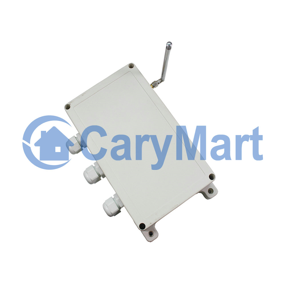
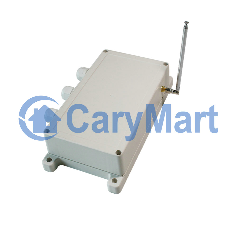
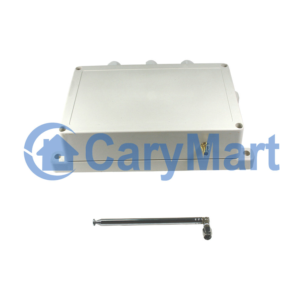
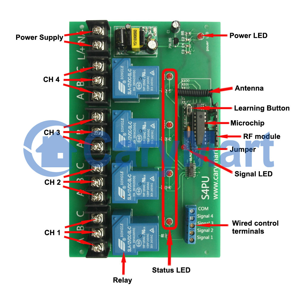
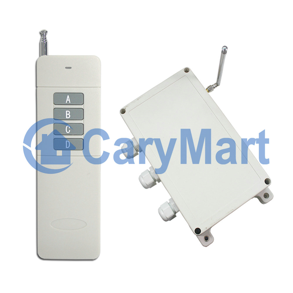
1 × Reciver: S4PU-AC-ANT3
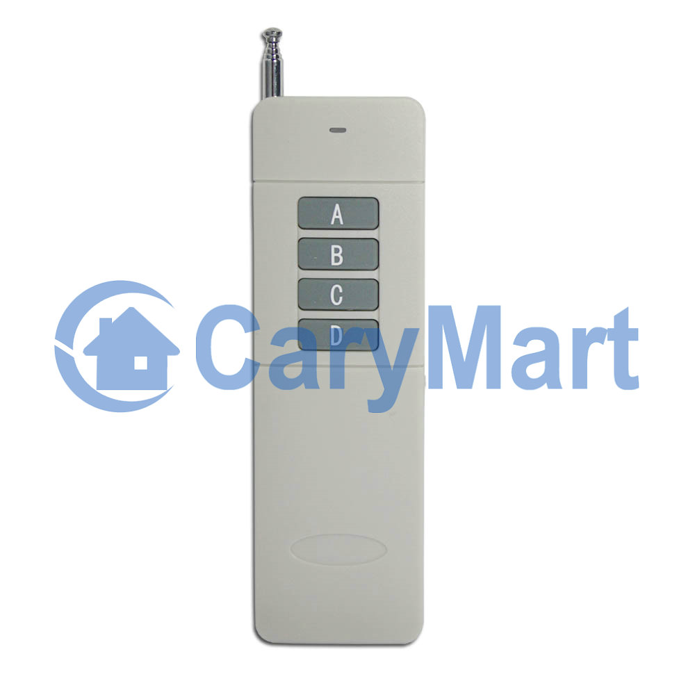
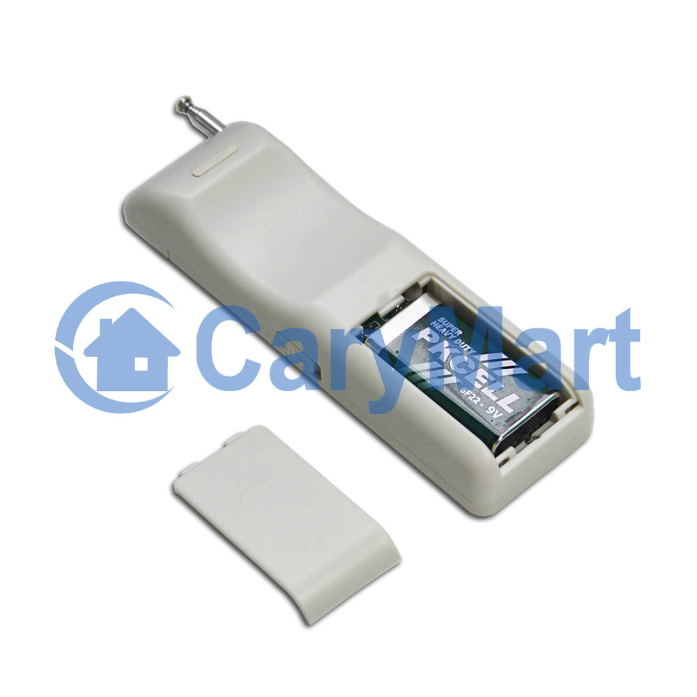
1 × Transmitter: CB-4
1 × User Manual
Feature:
Application: It can be used in industry automation, agriculture automation and home automation, such as factory, house, farm, pasture, vehicle, ship, offshore operation, aerial vehicle, field call, etc. It can remote control equipments on land, water and air, such as remote control lights, sirens, locks, motors, fans, winches, blinds, linear actuators, doors, windows, electric solenoid valves, security alarm, business signs and various devices.
Wireless remote control, easy to install.
Super long working range, with a transmitter to form a complete set, the working distance can reach 2000m in an open ground.
Waterproof: The receiver has
Universal input: Support voltage of AC110V (100V~120V), widely used in
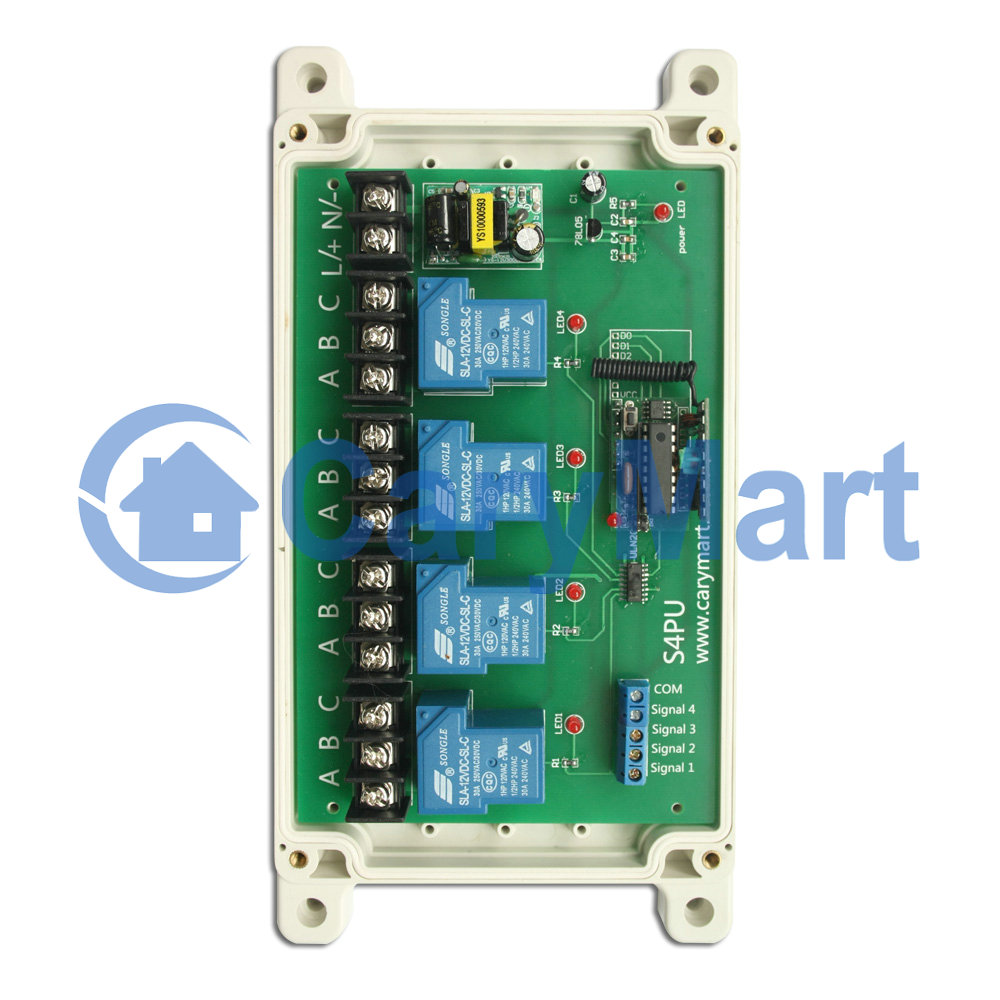
Relay Output: This receiver is relay output, it can be used to operate both DC and AC
High Power: Each channel can work at maximum current 30A.
With wired control terminals: You can connect sensors, limit switches, manual switches or external devices to control the receiver.
With
You can control the
Wireless RF signal can pass through walls, floors, doors or windows.
With characteristics of reverse power protection and over current protection.
One/several transmitters can control one/several receivers simultaneously.
You can use two or more units in the same place.
Receiver parameters:
Model No.: S4PU-AC-ANT3
Power Supply (Operating Voltage): AC100~240V (110V/120V/220V/240V)
Output: Relay output (Normally open and normally closed)
Control Modes: Self-locking, Momentary, Interlocking, Momentary + Self-locking
Working Frequency: 433MHz
Maximum Working Current: 30A / each channel
Static Current: ≤6mA
Operating Temperature: -20 ° C to +70 ° C
PCB size: 170mm x 109mm x 18mm
Case size: 200mm x 120mm x 53mm
Wire range for the terminals: 22-12AWG.
Transmitter Parameters:
Model No.: 0021026 (CB-4)
Channel/Button: 4
Button Symbol: A, B, C, D
Operating Voltage: 9V (1 x 6F22 -9V battery, can be used for 12 months)
Operating Current: 30mA
Transmitting Distance: 1000m / 3000ft (theoretically)
It has an on / off button on the side.
Modulation Mode: ASK
Unit Size: 135mm x 42mm x 25mm
External Telescopic Antenna ANT3 For Receiver:
Length of external telescopic antenna: 108mm / 445mm (stretch)
With SMA connector.
If you
Matching Transmitters For Receiver:
The receiver can pair different model transmitters, includes model C-4 (200M), CWB-4 (50M, waterproof), CP-4 (1000M) and CB-4 (2000M) etc...
The working range:
Super long range, with a transmitter (such as CB-4) to form a complete set, the maximum working distance can reach 2000M in an open ground.
The maximum working distance is an ideal range; it shall be operated with no barriers and interference in an open ground. But in the practice, it will be hindered by trees, walls or other constructions, and will be interfered by other wireless sign. Therefore, the actual distance may not reach this maximum working distance.
Usage (with the transmitter CB-4):
The receiver can be used to control both DC 0~28V and AC 110~240V
Notice: The receiver is relay output, not DC/AC power output.
Wiring:
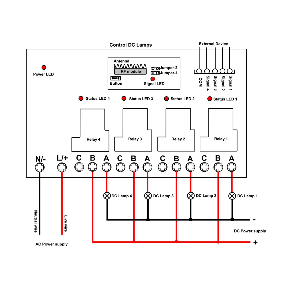
1) If you want to control a DC 12V lamp, do as following:
1.1 Connect the live wire of AC power supply to terminal “L / +”, and connect the neutral wire of AC power supply to terminal “N / -”.
1.2 Connect terminal B to the positive pole of DC power supply, connect terminal A to the positive pole of DC lamp, and connect the negative pole of DC lamp to the negative pole of DC power supply.
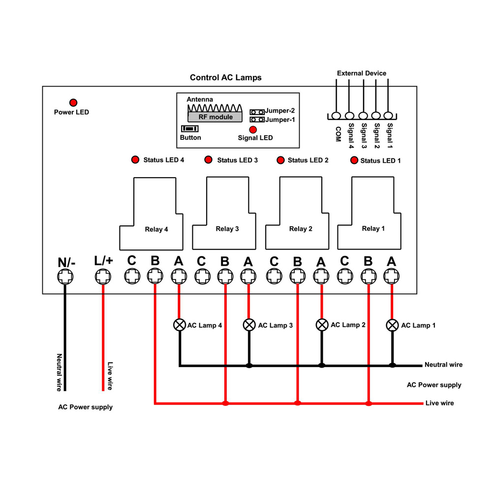
2) If you want to control an AC 220V lamp, do as following:
2.1 Connect the live wire of AC power supply to terminal “L / +”, and connect the neutral wire of AC power supply to terminal “N / -”.
2.2 Connect terminal B to the live wire of AC power supply, connect terminal A to one side of AC lamp, and connect another side of AC lamp to the neutral wire of AC power supply.
Setting different control modes:
We have set the receiver in Self-locking mode before
Setting control mode Interlocking: Disconnect Jumper-1 and Jumper-2.
Control mode Interlocking (Channel A, B, C, D): Press -> On, other relays Off; Press
Press button A: The relay 1 is activated (connect A and B, disconnect A and C), and the lamp 1 is turned on.
Other relays are deactivated (disconnect A and B, connect A and C), and other lamps are turned off.
Press button B: The relay 2 is activated (connect A and B, disconnect A and C), and the lamp 2 is turned on.
Other relays are deactivated (disconnect A and B, connect A and C), and other lamps are turned off.
Press button C: The relay 3 is activated (connect A and B, disconnect A and C), and the lamp 3 is turned on.
Other relays are deactivated (disconnect A and B, connect A and C), and other lamps are turned off.
Press button D: The relay 4 is activated (connect A and B, disconnect A and C), and the lamp 4 is turned on.
Other relays are deactivated (disconnect A and B, connect A and C), and other lamps are turned off.
Setting control mode Momentary: Only connect Jumper-1.
Control mode Momentary (Channel A, B, C, D): Press and hold -> On; Release -> Off.
Press and hold button A: The relay 1 is activated (connect A and B, disconnect A and C), and the lamp 1 is turned on.
Release button A: The relay 1 is deactivated (disconnect A and B, connect A and C), and the lamp 1 is turned off.
Press and hold button B: The relay 2 is activated (connect A and B, disconnect A and C), and the lamp 2 is turned on.
Release button B: The relay 2 is deactivated (disconnect A and B, connect A and C), and the lamp 2 is turned off.
Press and hold button C: The relay 3 is activated (connect A and B, disconnect A and C), and the lamp 3 is turned on.
Release button C: The relay 3 is deactivated (disconnect A and B, connect A and C), and the lamp 3 is turned off.
Press and hold button D: The relay 4 is activated (connect A and B, disconnect A and C), and the lamp 4 is turned on.
Release button D: The relay 4 is deactivated (disconnect A and B, connect A and C), and the lamp 4 is turned off.
Setting control mode Self-locking: Only connect Jumper-2.
Control mode Self-locking (Channel A, B, C, D): Press -> On; Press again -> Off.
Press button A: The relay 1 is activated (connect A and B, disconnect A and C), and the lamp 1 is turned on.
Press button A again: The relay 1 is deactivated (disconnect A and B, connect A and C), and the lamp 1 is turned off.
Press button B: The relay 2 is activated (connect A and B, disconnect A and C), and the lamp 2 is turned on.
Press button B again: The relay 2 is deactivated (disconnect A and B, connect A and C), and the lamp 2 is turned off.
Press button C: The relay 3 is activated (connect A and B, disconnect A and C), and the lamp 3 is turned on.
Press button C again: The relay 3 is deactivated (disconnect A and B, connect A and C), and the lamp 3 is turned off.
Press button D: The relay 4 is activated (connect A and B, disconnect A and C), and the lamp 4 is turned on.
Press button D again: The relay 4 is deactivated (disconnect A and B, connect A and C), and the lamp 4 is turned off.
Setting control mode Momentary + Self-locking: Connect Jumper-1 and Jumper-2.
Control mode Momentary (Channel A, B): Press and hold -> On; Release -> Off.
Press and hold button A: The relay 1 is activated (connect A and B, disconnect A and C), and the lamp 1 is turned on.
Release button A: The relay 1 is deactivated (disconnect A and B, connect A and C), and the lamp 1 is turned off.
Press and hold button B: The relay 2 is activated (connect A and B, disconnect A and C), and the lamp2 is turned on.
Release button B: The relay 2 is deactivated (disconnect A and B, connect A and C), and the lamp 2 is turned off.
Control mode Self-locking (Channel C, D): Press -> On; Press again -> Off.
Press button C: The relay 3 is activated (connect A and B, disconnect A and C), and the lamp 3 is turned on.
Press button C again: The relay 3 is deactivated (disconnect A and B, connect A and C), and the lamp 3 is turned off.
Press button D: The relay 4 is activated (connect A and B, disconnect A and C), and the lamp 4 is turned on.
Press button D again: The relay 4 is deactivated (disconnect A and B, connect A and C), and the lamp 4 is turned off.
Wired control terminals:
The receiver has wired control terminals, and you can connect external devices, sensors, or manual switches to the receiver's manual terminals, then use them to trigger the receiver.
1) By
You can connect external devices (with
When the external device outputs
When the external device outputs
When the external device outputs
When the external device outputs
2) By NO/NC contact:
You can connect manual switches (with NO/NC contact) to trigger the receiver.
When
When
When
When

Home | How To Buy | Specials | About Us | Sitemap | Contact Us | FAQs
Copyright @ 2012-2024 Remote Control System Store. Powered byCaryMart