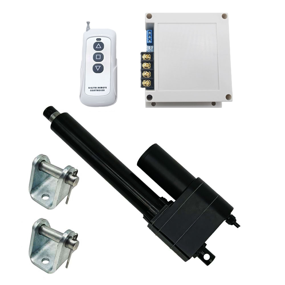
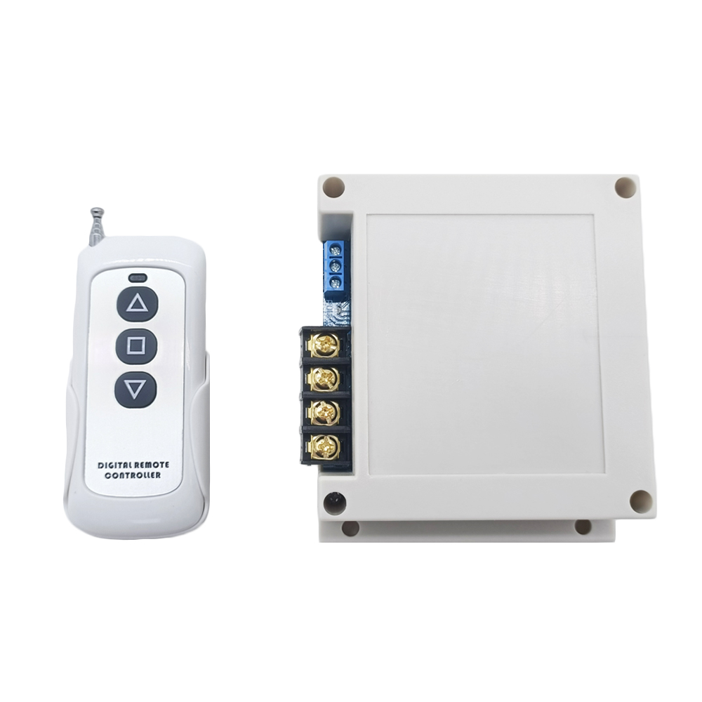
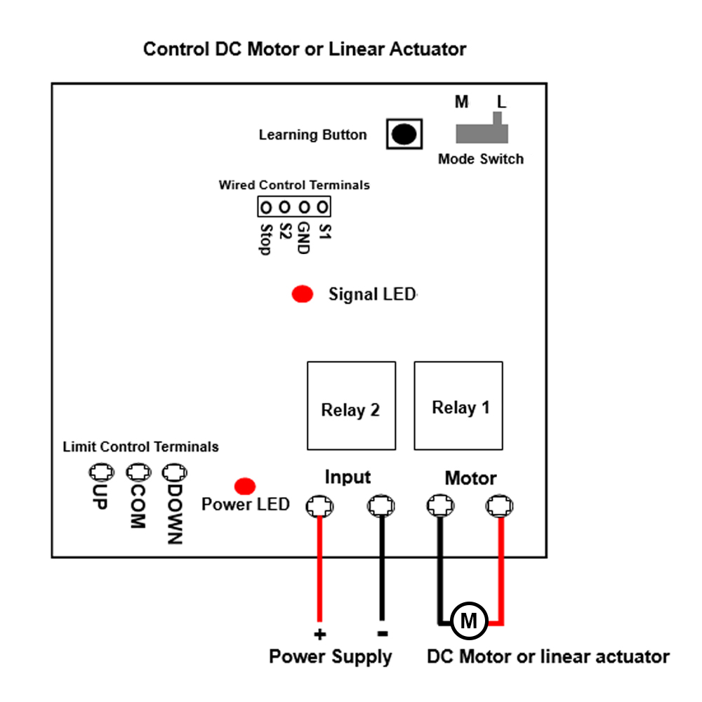
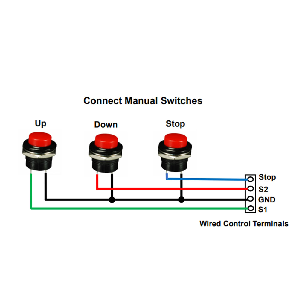
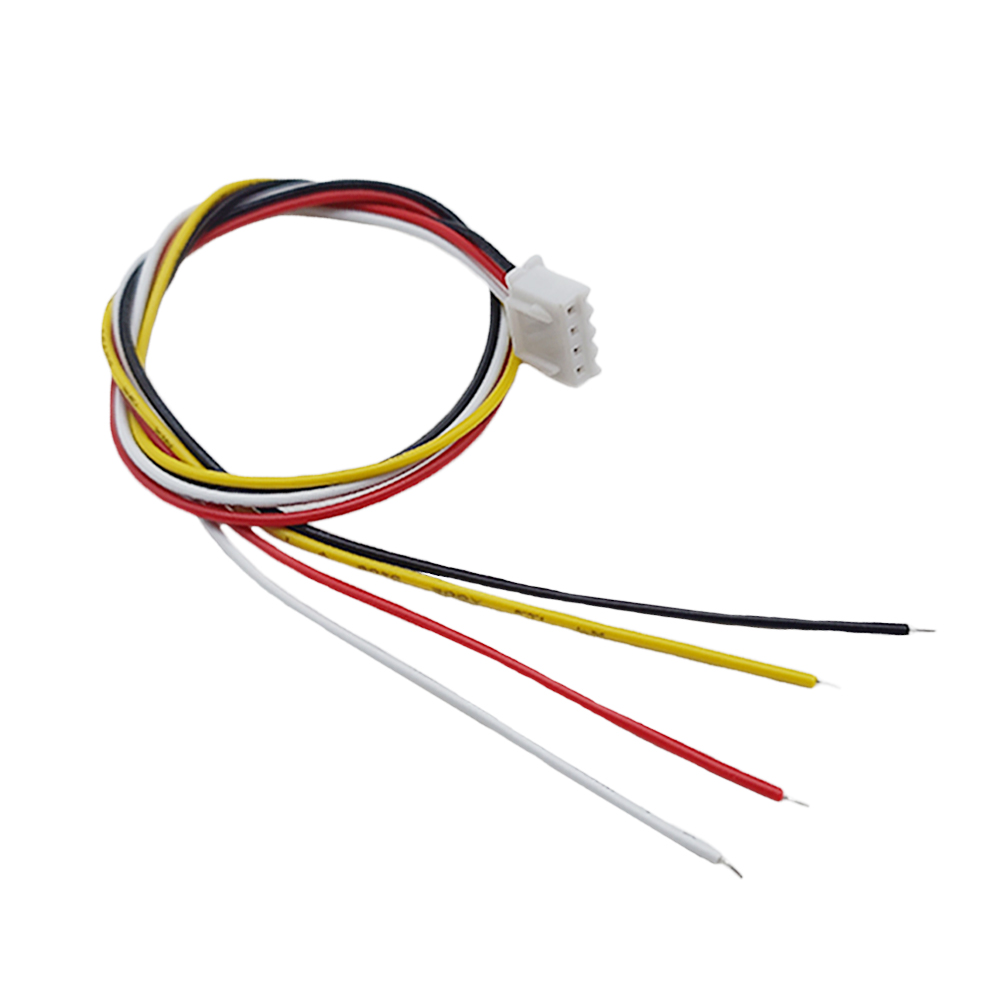
The receiver has wired control terminals, and you can connect external devices (with normally open contact), such as manual switches to wired control terminals, then use them to control the motor or the linear actuator.
For example, you can connect three manual switches to wired control terminals S1, S2, STOP and GND according to following wiring diagram.
1) In Interlocking mode: For example, connect 3 pushbutton manual switch (Model 0040024).
When pressing the UP button, two terminals S1 and GND are connected, then the motor rotates in the positive direction, or the linear actuator extends outward. And when pressing the STOP button, two terminals STOP and GND are connected, then the motor or linear actuator stops.
When pressing the DOWN button, two terminals S2 and GND are connected, then the motor rotates reversal direction, or the linear actuator inward retracts. And when pressing the STOP button, two terminals STOP and GND are connected, then the motor or linear actuator stops.
2) In Momentary mode: For example, connect 2 pushbutton manual switch (Model 0040025).
When pressing and holding the UP button, two terminals S1 and GND are connected, then the motor rotates in the positive direction, or the linear actuator extends outward. And when releasing the UP button, two terminals S1 and GND are disconnected, then the motor or linear actuator stops.
When pressing and holding the DOWN button, two terminals S2 and GND are connected, then the motor rotates reversal direction, or the linear actuator inward retracts. And when releasing the DOWN button, two terminals S2 and GND are disconnected, then the motor or linear actuator stops.