Hi, I'm Tom. Welcome to our shop,
Carymart offers you the premium rf remote control equipment.
We suggest you reading our FAQs before making your decision.
If you have any other question, please contact us.
We will reply you as soon as possible.
Application:
By using this motor remote control kit, you can remote control DC motor in
high power. The motor remote control kit is suitable for the motors of
rolling blinds / doors, projection screens, awnings, pumps, winches,
conveyors or other appliances and machines. Remote control distance is up to
1000M.
Features:
Application: It can be used in rolling blinds, rolling doors, projection
screens, awnings, pumps, winches, conveyors or other appliances and
equipments with DC motors, it can remote control DC motor rotates in the
positive or reversal direction.
Wireless control, easy to install.
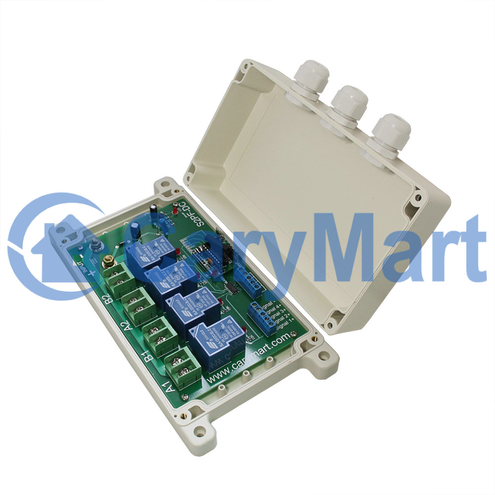
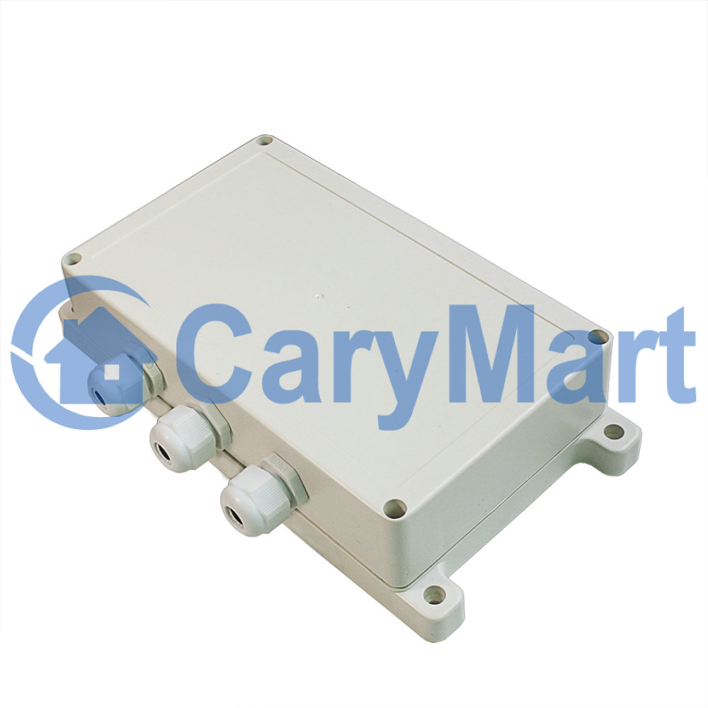
Waterproof: The receiver has waterproof case and waterproof connector, it
can be installed outdoors.
You can rotate two motors separately in the positive or reversal direction
with the transmitter (remote control) from any place within a reliable
distance. The RF wireless signal can pass through walls, floors and doors.
High Power: Each channel can work at maximum current 30A.
With limit control terminals: You can connect limit switches or sensors to
stop the motor.
With wired control terminals: You can connect manual switches or external
devices (with low level output signal, such as sensors) to control the
motor.
Use an 8-bit microprocessor designed and developed with low-power and
high-speed CMOS technology.
With characteristics of reverse power protection and over current
protection.
Reliable control: The receiver only works with the transmitter which use
same code.
One/several transmitters can control one/several receivers simultaneously.
You can use two or more units in the same place.
Receiver Parameters:
Model No: S2PF-DC06 / S2PF-DC09 / S2PF-DC12 / S2PF-DC24
Control Modes: Momentary, Interlocking,
Coding Type: Fixed code or learning code
Coding Setting: By learning
Power Supply (Operating Voltage): DC6V (S2PF-DC06), DC9V±1V (S2PF-DC09),
DC12V±1V (S2PF-DC12), DC24V±1V (S2PF-DC24)
Output: DC6V (S2PF-DC06), DC9V (S2PF-DC09), DC12V (S2PF-DC12), DC24V
(S2PF-DC24)
Working Frequency: 433MHz
Channel: 2 CH, can work with 2 DC motors
Static Current: ≤6mA
Maximum Working Current: 30A / each channel, so motor's maximum starting
current can not exceed 30A.
PCB Size: 170mm x 109mm x 25mm
Case Size: 200mm x 120mm x 53mm
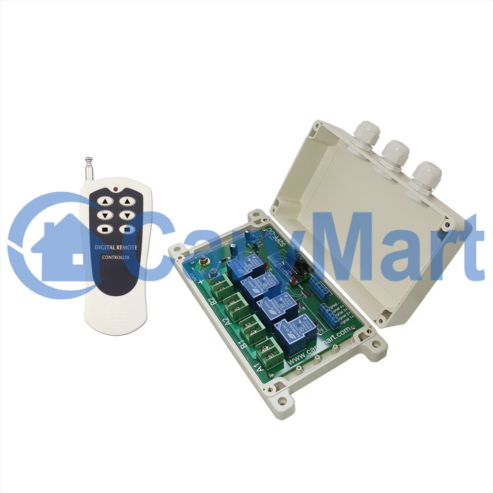
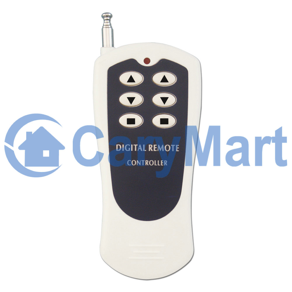
Transmitter Parameters:
Model: 0021052 (CV-6-2)
Shell Color: White
Button Symbol: Two▲, Two▼, Two■
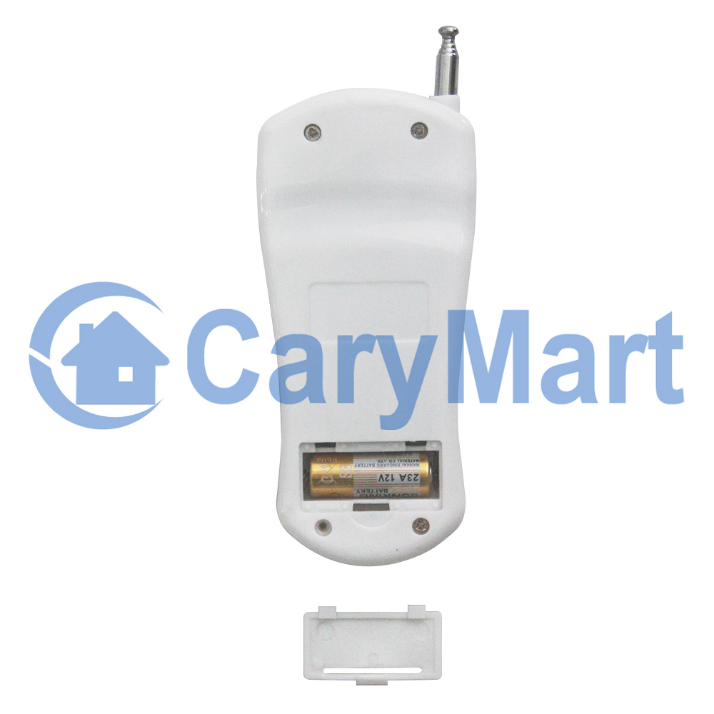
Operating Voltage: 12V (1 x 23A -12V battery, can be used for 12 months)
Operating Current: 15mA
Operating Frequency: 433Mhz
Encoding Chip: LX2260A-R4
Encoding Type: Fixed code by soldering, up to 6561 codes
Transmitting Distance: 500m / 1500ft (theoretically)
Modulation Mode: ASK
Operating Temperature: -20 ° C to +70 ° C
Unit Size: 110mm x 50mm x 18mm
Working Range:
With a transmitter (such as
CV-6-2
) to form a complete set, the working
distance can reach 500M in an open ground. The maximum working distance 500M
is a theoretical data, it shall be operated in an open ground, no barriers,
no any interference. But in the practice, it will be hindered by trees,
walls or other constructions, and will be interfered by other wireless
signals. Therefore, the actual distance may or may not reach 500M. If you
want to have a further working range, you can install an external antenna to
the receiver.
Usage:
The receiver can be used to control DC 06V / 09V / 12V / 24V motor or linear
actuator. If the power supply of those equipments is DC 12V, you should
choose the receiver with same DC 12V version; and if the power supply of
those equipments is DC 24V, you should choose the receiver with same DC 24V
version.
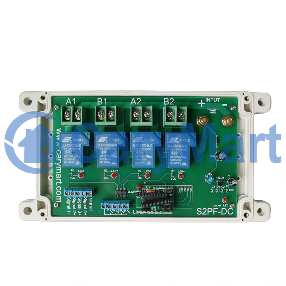
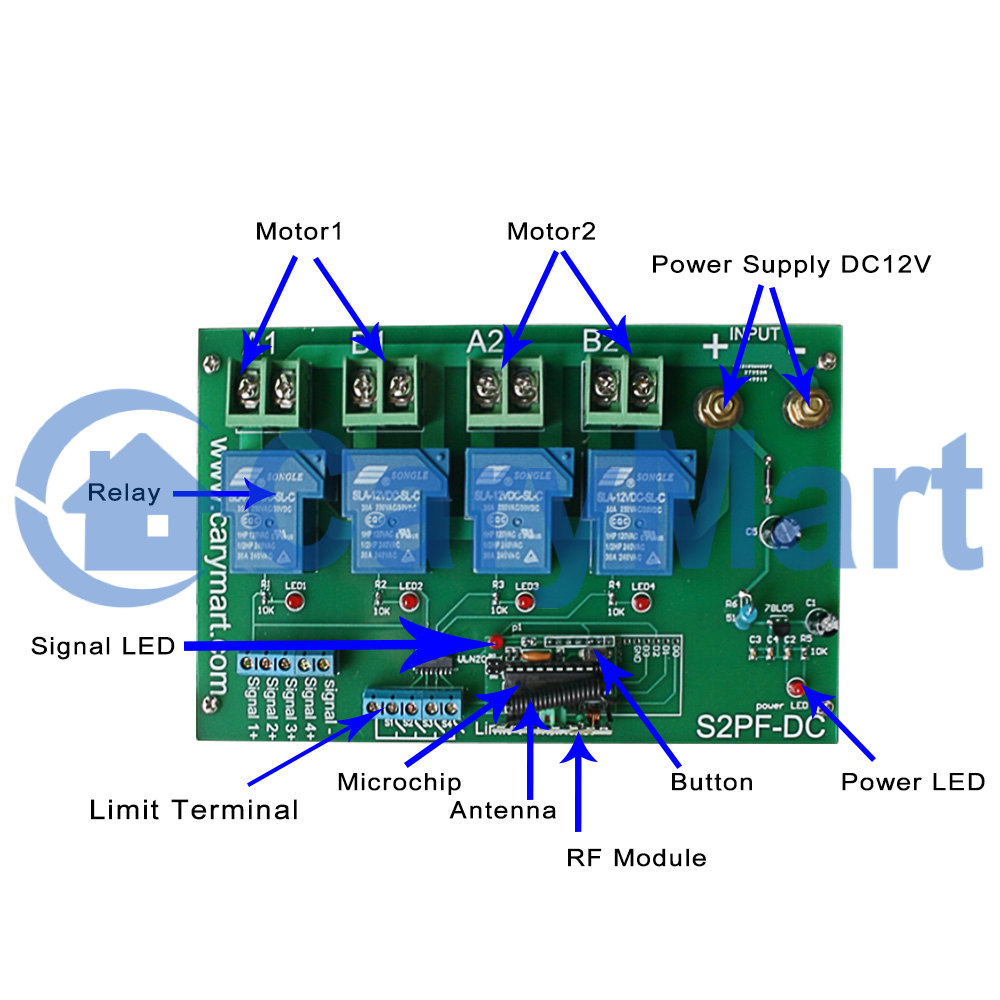
Wiring:
1) Connect the positive pole of DC power supply to terminal “+” of INPUT, and
connect the negative pole of DC power supply to terminal “-” of INPUT.
2) Connect terminals “A1” and “B1” to motor 1; connect terminals “A2” and “B2”
to motor 2. You can exchange motor's two wires to change the rotating
direction of motor.
Setting different working modes:
The receiver will be set in Interlocking mode before leaving the factory, if
you require momentary mode, please follow the following steps.
Setting Interlocking mode: Do not connect Jumper-1 (CN1) or Jumper-2 (CN2)
Press button ▲ on the left: motor 1 rotates in positive direction.
Press button ▼ on the left: motor 1 rotates in reversal direction.
Press button ■ on the left: motor 1 stops.
Press button ▲ on the right: motor 2 rotates in positive direction.
Press button ▼ on the right: motor 2 rotates in reversal direction.
Press button ■ on the right: motor 2 stops.
Setting Momentary mode: Only connect Jumper-1 (CN1)
Press and hold button ▲ on the left: motor 1 rotates in positive direction.
Release button ▲ on the left: motor 1 stops.
Press and hold button▼ on the left: motor 1 rotates in reversal direction.
Release button ▼ on the left: motor 1 stops.
Press and hold button ▲ on the right: motor 2 rotates in positive direction.
Release button▲ on the right: motor 2 stops.
Press and hold button▼ on the right: motor 2 rotates in reversal direction.
Release button ▼ on the right: motor 2 stops.
Limit control terminals:
Limit control terminals S1, S2, S3 and S4 are normally open, you can connect
limit switches or sensors (normally open type) to terminals S1, S2, S3 and
S4, and then you can use limit switches or sensors to stop the motor.
When motor 1 rotates in positive direction, if connect two terminals of S1,
the motor 1 will stop automatically.
When motor 1 rotates reversal direction, if connect two terminals of S2, the
motor 1 will stop automatically.
When motor 2 rotates in positive direction, if connect two terminals of S3,
the motor 2 will stop automatically.
When motor 2 rotates reversal direction, if connect two terminals of S4, the
motor 2 will stop automatically.
Wired control terminals:
You can connect manual switches, external devices or sensors (with low level
output signal) to control the motor.
1) The manual switches:
You can connect manual switches to terminals “Signal-”, “Signal 1+”, “Signal
2+”, “Signal 3+”, “Signal 4+”, then you can use manual switches to control
the motor.
When connect terminals “Signal 1+” and “Signal-”, motor 1 rotates in
positive direction. And when disconnect “Signal 1+” and “Signal-”, motor 1
stops.
When connect terminals “Signal 2+” and “Signal-”, motor 1 rotates in
reversal direction. And when disconnect “Signal 2+” and “Signal-”, motor 1
stops.
When connect terminals “Signal 3+” and “Signal-”, motor 2 rotates in
positive direction. And when disconnect “Signal 3+” and “Signal-”, motor 2
stops.
When connect terminals “Signal 4+” and “Signal-”, motor 2 rotates in
reversal direction. And when disconnect “Signal 4+” and “Signal-”, motor 2
stops.
2) Signal input:
You can connect external devices (with low level output signal) to terminals
“Signal-”, “Signal 1+”, “Signal 2+”, “Signal 3+”, “Signal 4+”, then the
external device’s output signal can control the motor.
When the external device outputs low level signal to terminal “Signal-” and
“Signal 1+“, motor 1 rotates in positive direction.
When the external device outputs low level signal to terminal “Signal-” and
“Signal 2+“, motor 1 rotates in reversal direction.
When the external device outputs low level signal to terminal “Signal-” and
“Signal 3+“, motor 2 rotates in positive direction.
When the external device outputs low level signal to terminal “Signal-” and
“Signal 4+“, motor 2 rotates in reversal direction.
Package Include:
1 x Receiver: S2PF-DC06 / S2PF-DC09 / S2PF-DC12 / S2PF-DC24
1 x Transmitter: CV-6-2
1 x User manual