Hi, I'm Tom. Welcome to our shop,
Carymart offers you the premium rf remote control equipment.
We suggest you reading our FAQs before making your decision.
If you have any other question, please contact us.
We will reply you as soon as possible.
Application:
This receiver is an electric device with relay output that can be used in
one-transmitter-many-receivers system. For example, you can use a 1 button
transmitter to control 1 receiver, or use a 2 buttons transmitter to control
2 receivers, or use a 4 buttons transmitter to control 4 receivers, or use a
6 buttons transmitter to control 6 receivers, or use an 8 buttons
transmitter to control 8 receivers, or use a 12 buttons transmitter to
control 12 receivers. The transmitter and receiver form a wireless
remote-control system. This system may be used in all types of industry
automation, agriculture, business, home, factory, house, farm, garage,
vehicle, ship, aerial vehicle, etc. It can remote control different DC or AC
equipment on land, water, and air, such as lights, doors, windows, lamps,
sockets, locks, sirens, outlets, heaters, motors, fans, winches, curtains,
blinds, linear actuators, electric solenoid valves, and security alarm
systems. The applications are endless.
Feature:
Wireless control, easy to install.
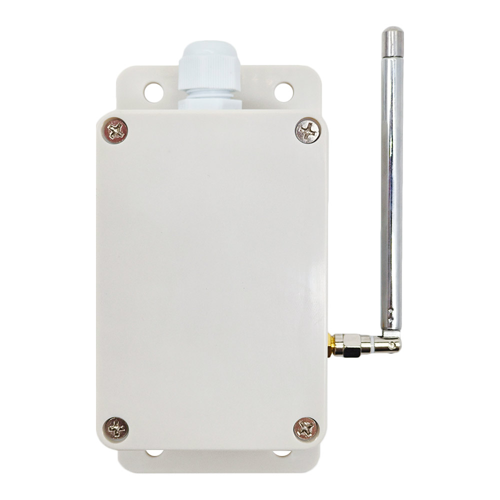
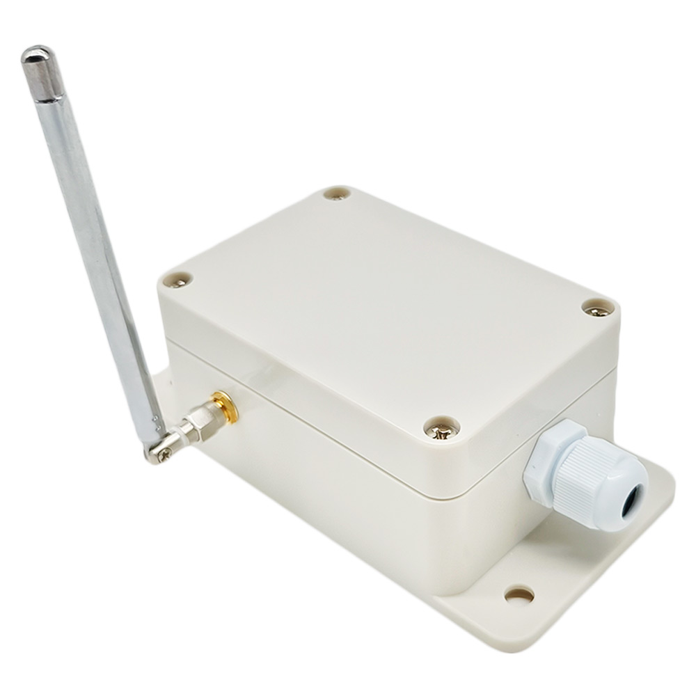
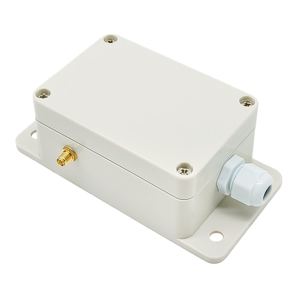
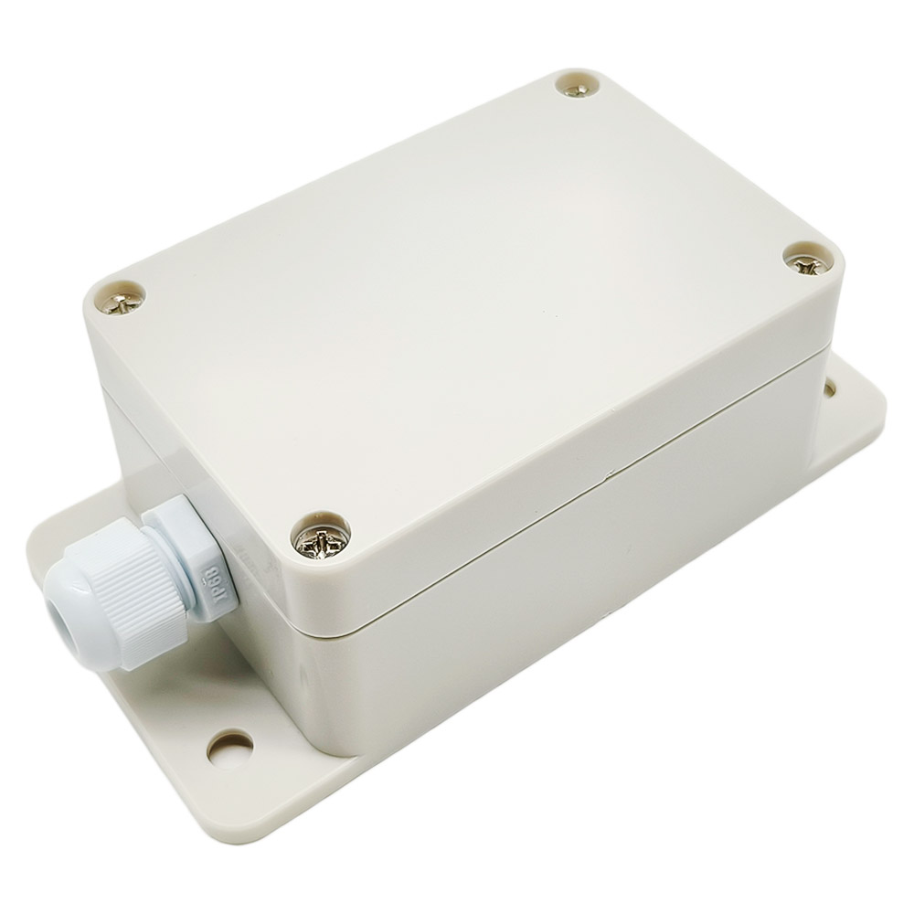
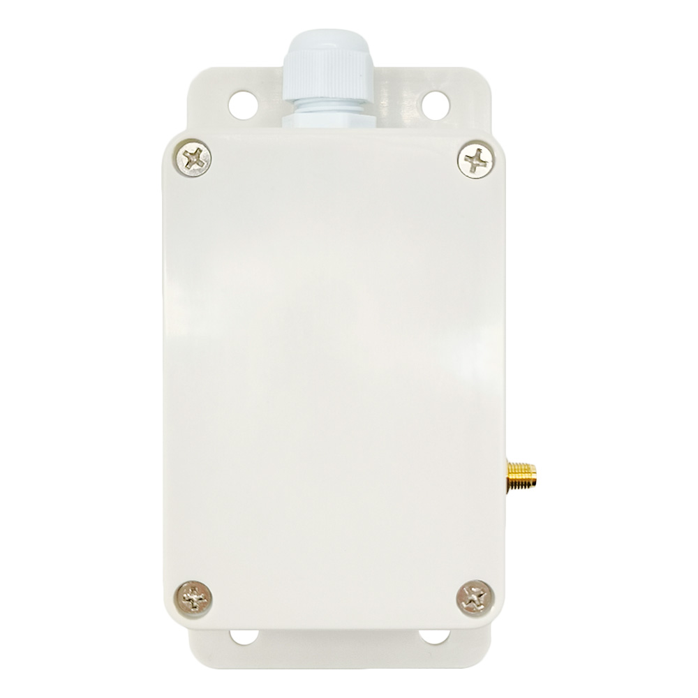
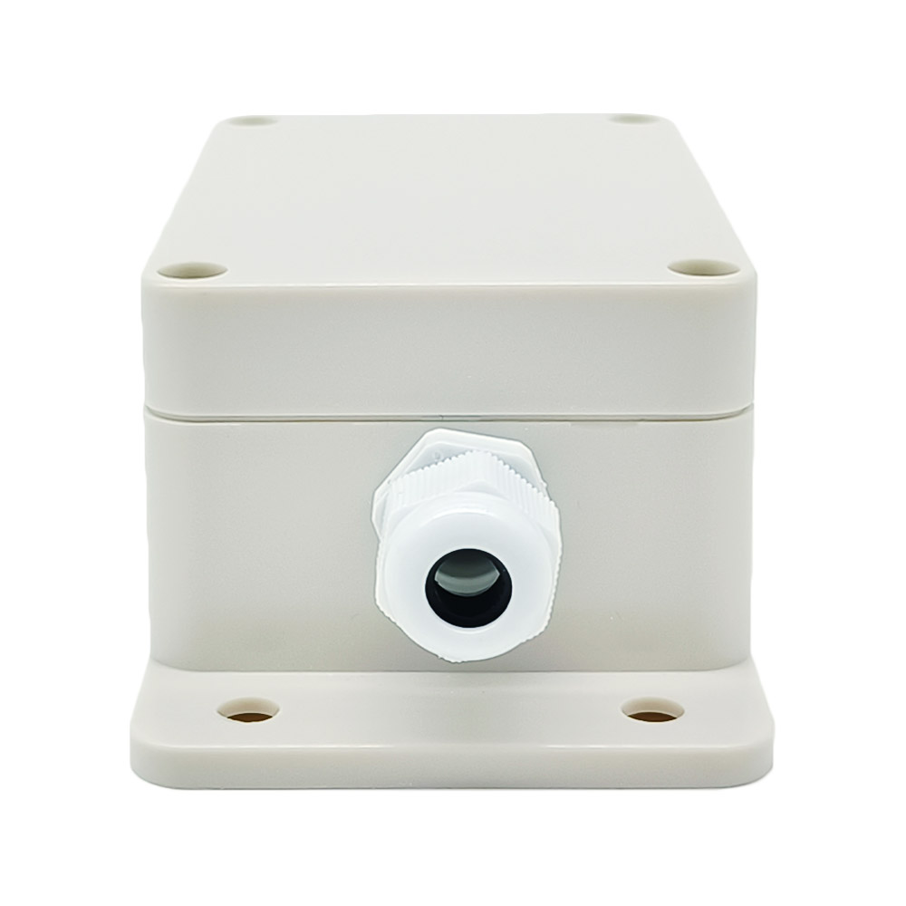
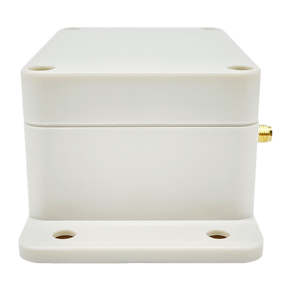
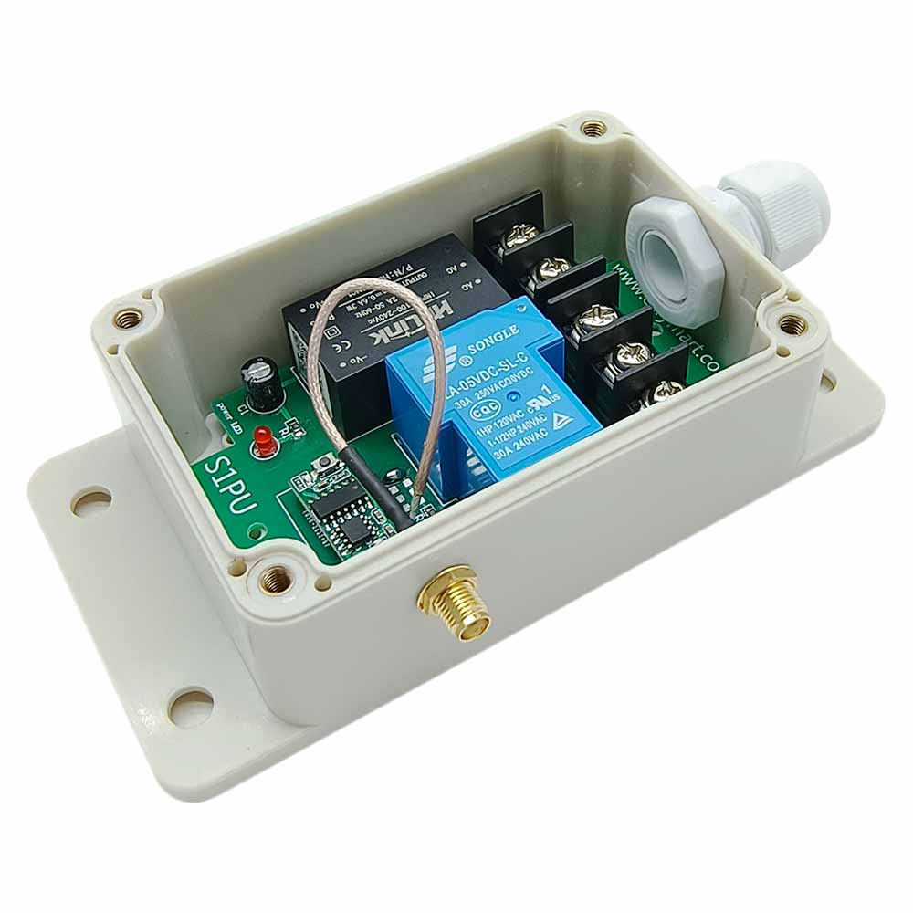
Waterproof: The receiver has waterproof case and waterproof connector, it
can be installed outdoors.
Universal input: Support 110V AC (110V~120V) used in US, Canada, etc, and
220V AC (220V~240V) used in Germany, UK, France, etc.
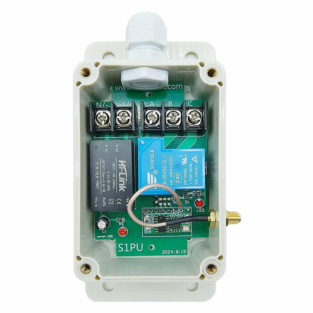
Relay Output: This receiver is dry relay output; it can be used to operate
both DC and AC equipment. The output terminals are NO / NC (normally open /
normally closed), serving as a switch. That means you should also connect a
separate power supply to equipment.
High Power: Each channel can work at maximum current 30A.
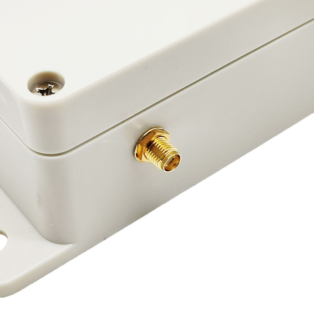
With external antenna, the receiver has a farther working range.
The transmitter / remote can control the receiver from any place within a
reliable working distance.
Wireless RF signal from the transmitter can pass through walls, floors,
doors, or windows, but it will lose some operating range.
The receiver has reverse voltage protection and overcurrent protection.
The receiver can only be triggered by paired transmitters.
Two or more receivers may be used in the same area.
One or more transmitters / remotes can control one or several receivers
simultaneously.
You can use one transmitter to control multiple receivers, and each
transmitter button controlling one receiver. For example, you can use a 1
button transmitter to control 1 receiver, or use a 2 buttons transmitter to
control 2 receivers, or use a 4 buttons transmitter to control 4 receivers,
or use a 6 buttons transmitter to control 6 receivers, or use an 8 buttons
transmitter to control 8 receivers, or use a 12 buttons transmitter to
control 12 receivers, etc.
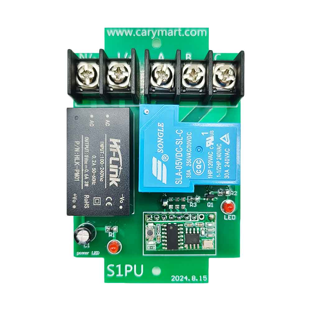
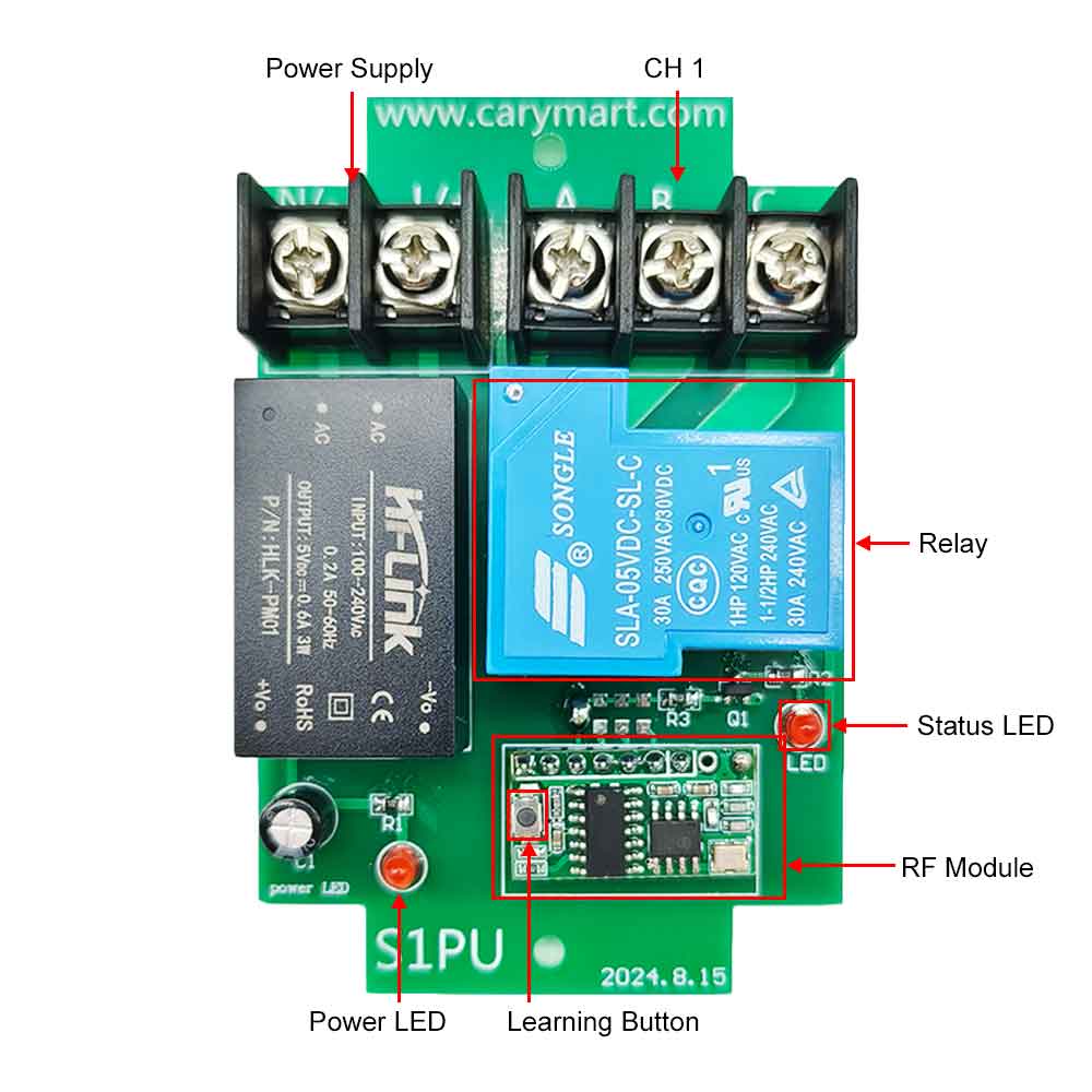
Receiver Parameters:
Model: S1PU-AC-ANT3
Operating Voltage: 110~240V AC (110V/120V/220V/240V)
Working Frequency: 433.92 MHz
Quiescent Current: ≤6mA
Channel: 1 CH
Output Type: Relay Output (With Normally Open and Normally Closed Terminals)
Maximum Load Voltage of Relay: 240VAC or 28VDC
Maximum Load Current of Relay: 30A / channel
Suitable Wires for Connecting Terminals: 22-12 AWG
3 Selectable Working Modes: Self-locking, Momentary, Interlocking
Operating Temperature: -20 °C ~ +70 °C
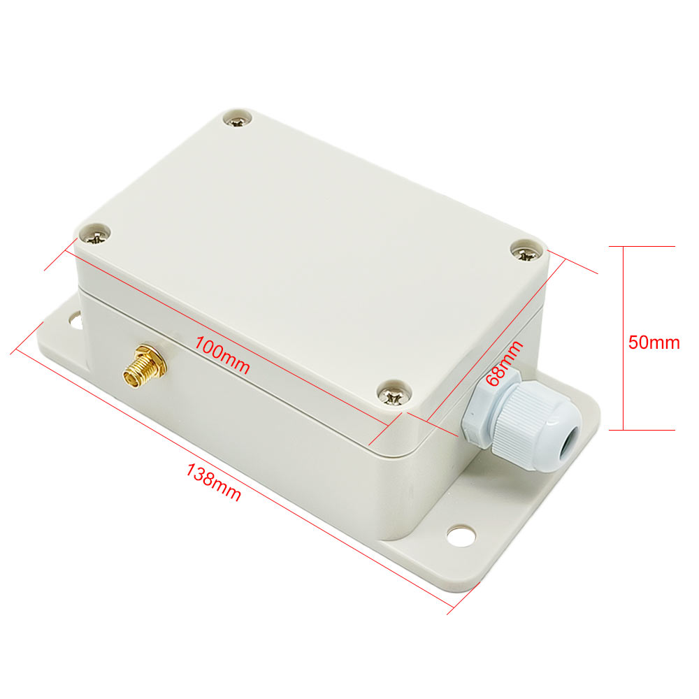
PCB size: 90 x 59 x 18 mm (3.5 x 2.3 x 0.7 inches)
Case size: 138 x 68 x 50 mm (5.4 x 2.7 x 2.0 inches)
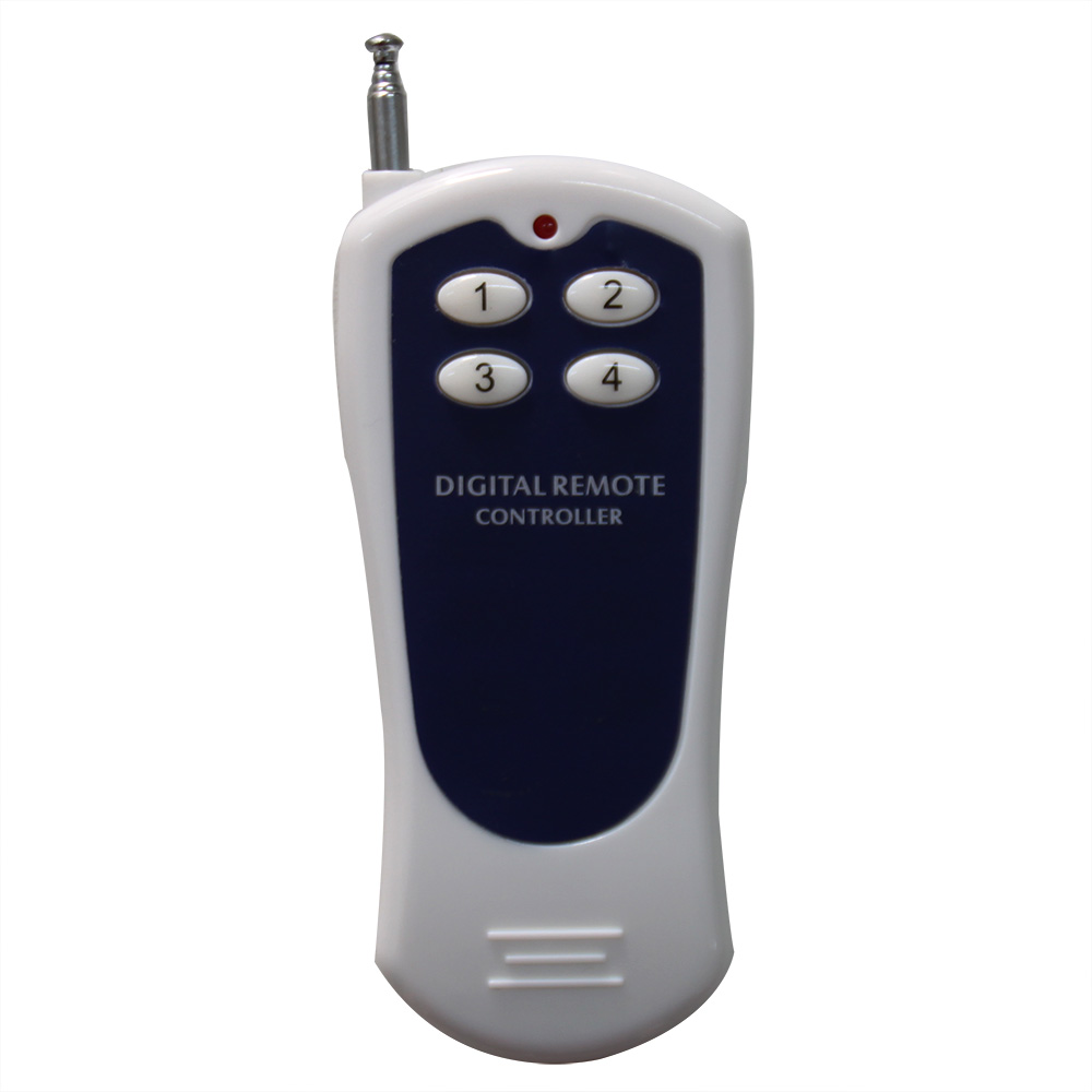
Transmitter Parameters:
Model: 0021018 (CV-4)
Channel / Button: 4
Button Symbol: 1, 2, 3, 4
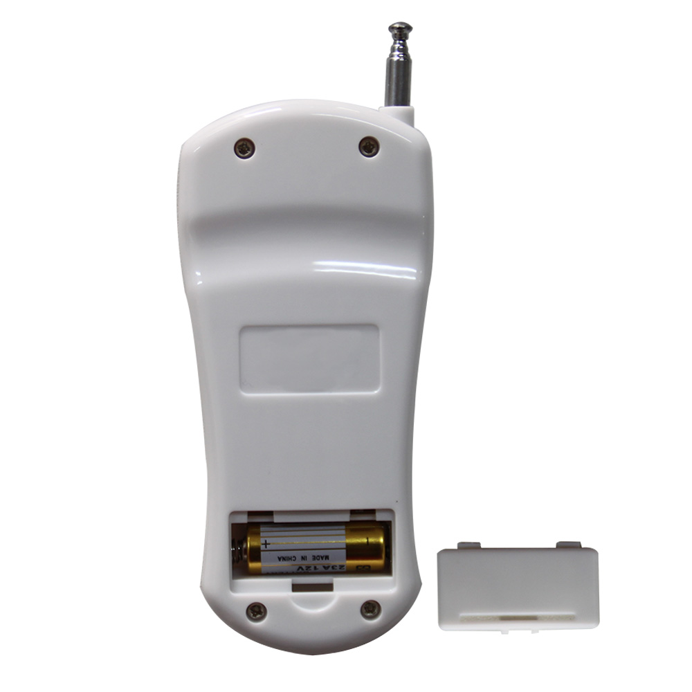
Operating Voltage: 12V (1 x 23A -12V battery, can be used for 12 months)
Operating Current: 15mA
Encoding Chip:PT2264/PT2262/SC2262
Transmitting Distance: 500m / 1500ft (theoretically)
Modulation Mode: ASK
Operating Temperature: -20 ° C to +70 ° C
Unit Size: 110 x 50 x 18 mm
Matching Transmitters:
The receiver can work with different transmitters, such as model
C-4
(100M),
CWB-4
(50M, waterproof),
CP-4
/
CV-4
(500M) and
CB-4
(1000M) etc.
Working Range:
With a transmitter (such as CV-4) to form a complete set, the maximum working
distance can reach 1500 feet or 500 meters in an open area.
The maximum working distance is a theoretical data, it shall be operated in
an open ground, no barriers, no interference. But in the practice, it will
be hindered by trees, walls, or other construction, and will be interfered
by other wireless signals. Therefore, the actual working distance may not
reach this maximum distance.
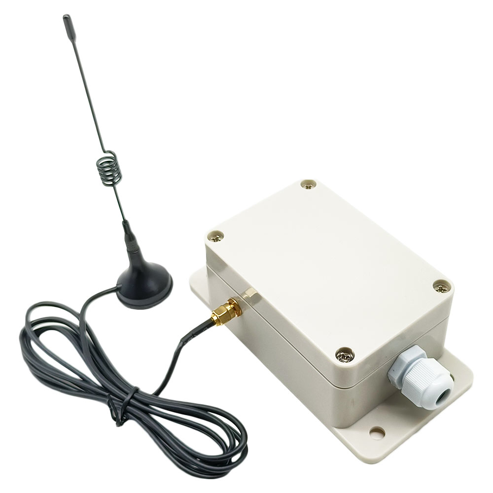
If you need a longer working distance, you can replace the antenna on the
receiver, or use an RF signal repeater, or use a powerful transmitter, such
as a CB-4 transmitter.
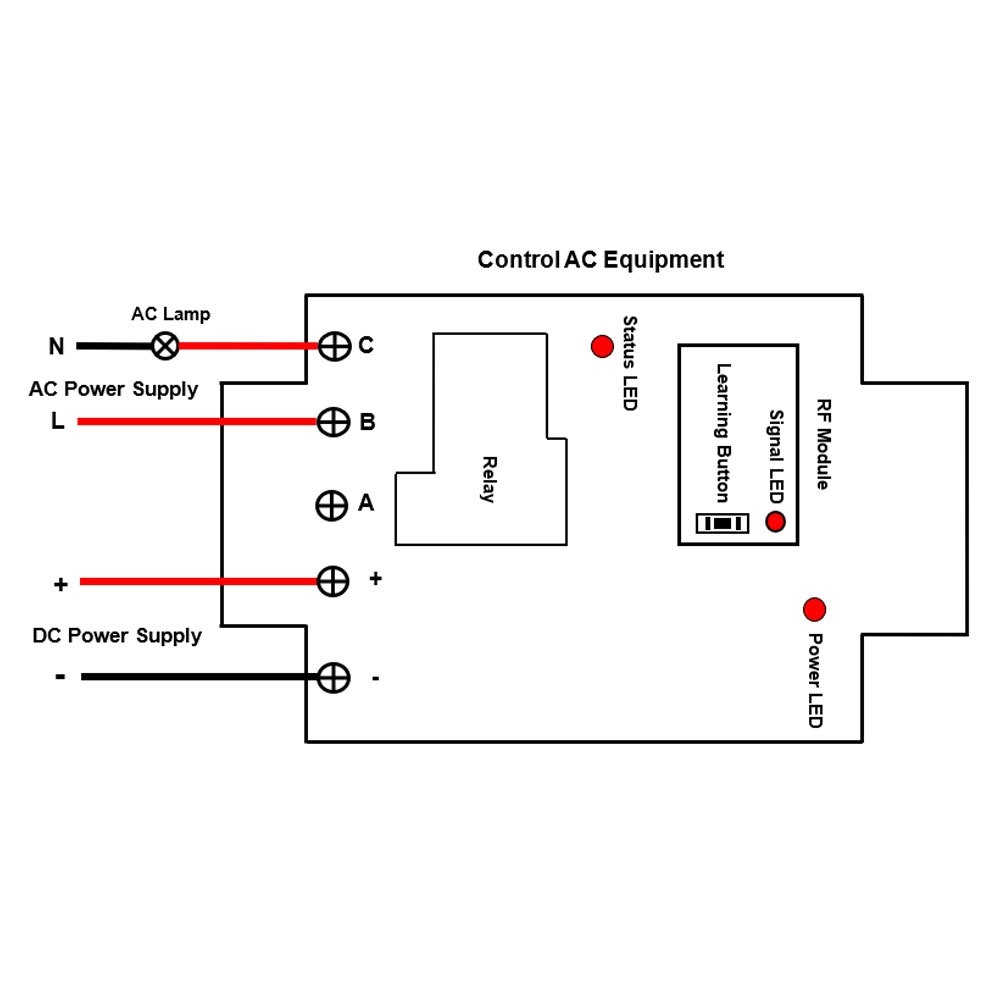
Usage:
The receiver can be used to control both 0~28VDC and 110~240VAC devices.
Notice: The receiver is relay output, not DC/AC power output. Initial state
of relay output terminals: Terminals B and C are Normally Open;
Terminals A and C are Normally Closed.
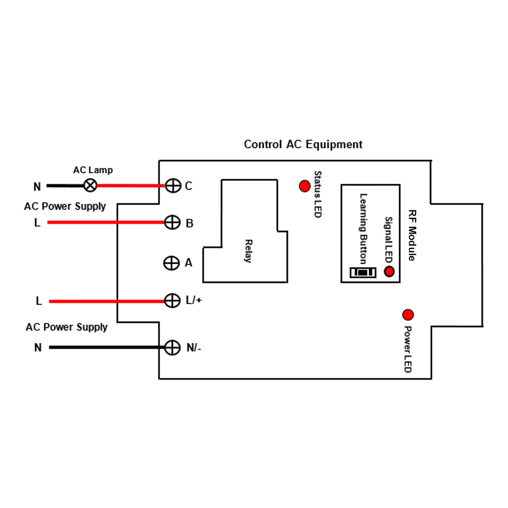
Wiring:
1) If you want to control a DC 12V lamp, do as following:
1.1 Connect the live wire of AC power supply to terminal L/+, and connect
the neutral wire of AC power supply to terminal N/-.
1.2 Connect terminal B to the positive pole of DC power supply, connect
terminal C to the positive pole of DC lamp, and connect the negative pole
of DC lamp to the negative pole of DC power supply.
2) If you want to control an AC 220V lamp, do as following:
2.1 Connect the live wire of AC power supply to terminal L/+, and connect
the neutral wire of AC power supply to terminal N/-.
2.2 Connect terminal B to the live wire of AC power supply, connect
terminal C to one side of AC lamp, and connect another side of AC lamp to
the neutral wire of AC power supply.
Setting different control modes:
The receiver will be set in Self-locking mode before leaving the factory, if
you want to use another mode, please follow the following steps.
1) Setting Momentary mode: Press the learning button in the receiver 2
times, signal LED continuously flashes 2 times and then goes off.
The operation of Momentary mode with the transmitter CV-4:
Press and hold the button 1 on the transmitter: The relay in the receiver 1
is activated, and the connected lamp 1 is turned on.
Release the button 1: The relay in the receiver 1 is deactivated, and the
connected lamp 1 is turned off.
......
Press and hold the button 4 on the transmitter: The relay in the receiver 4
is activated, and the connected lamp 4 is turned on.
Release the button D: The relay in the receiver 4 is deactivated, and the
connected lamp 4 is turned off.
2) Setting Self-locking mode: Press the learning button in the receiver 3
times, signal LED continuously flashes 3 times and then goes off.
The operation of Self-locking mode with the transmitter CV-4:
Press the button 1 on the transmitter: The relay in the receiver 1 is
activated, and the connected lamp 1 is turned on.
Press the button 1 again: The relay in the receiver 1 is deactivated, and
the connected lamp 1 is turned off.
......
Press the button 4 on the transmitter: The relay in the receiver 4 is
activated, and the connected lamp 4 is turned on.
Press the button 4 again: The relay in the receiver 4 is deactivated, and
the connected lamp 4 is turned off.
3) Setting Interlocking mode: Press the learning button in the receiver 4
times, signal LED continuously flashes 4 times and then goes off.
The operation of Interlocking mode with the transmitter CV-4:
Press the button 1 on the transmitter: The relay in the receiver 1 is
activated, and the connected lamp 1 is turned on. The relays on the other 3
receivers are deactivated, and the 3 connected lamps are turned off.
......
Press the button 4 on the transmitter: The relay in the receiver 4 is
activated, and the connected lamp 4 is turned on. The relays on the other 3
receivers are deactivated, and the 3 connected lamps are turned off.
How to pair the transmitter to the receiver:
Notice: We have paired the transmitter to the receiver before leaving the
factory.
You can freely pair any button on the transmitter with the receiver you want
to control.
1) Select the receiver to be controlled and press the learning button in the
receiver once, the signal LED on the receiver flashes once and then stays
on, it means the receiver enters the learning state.
2) Press the button you want to use on the transmitter, if the signal LED
flashes for 1 time, it means this button pairing is successful.
3) Press the learning button of receiver again for 1-2 seconds, the LED
signal turns off, it means the receiver exits the learning state.
4) The receiver can learn multiple transmitters with different codes.
How to delete all transmitters codes stored in the receiver:
Notice: We have paired the transmitter to the receiver, if you don’t want
the receiver to work with the transmitter, you can delete all transmitters
codes stored in the receiver.
Operation: Press the learning button in the receiver 10 times and then
release the learning button, signal LED flashes 10 times quickly and then
goes off, this indicates that all stored codes have been deleted
successfully.
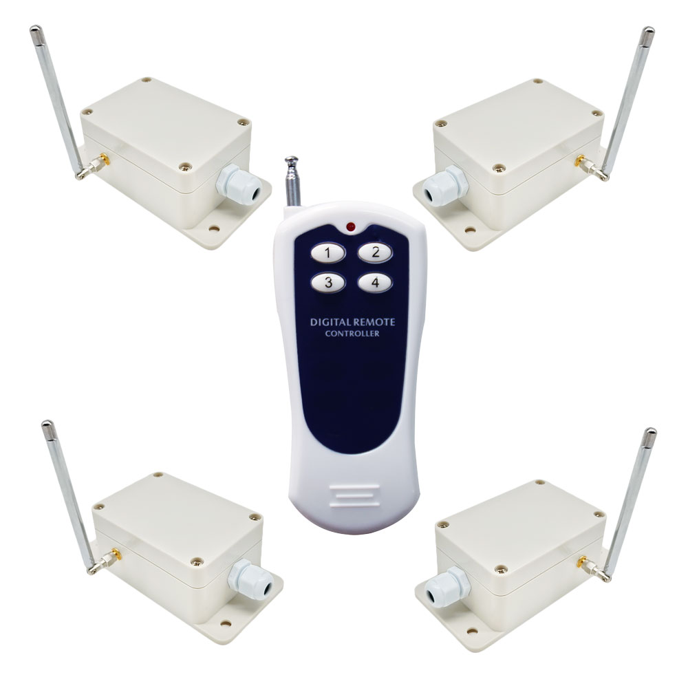
Package Include:
4 x Receiver: S1PU-AC-ANT3
1 x Transmitter: CV-4
1 x User manual