Hi, I'm Tom. Welcome to our shop,
Carymart offers you the premium rf remote control equipment.
We suggest you reading our FAQs before making your decision.
If you have any other question, please contact us.
We will reply you as soon as possible.
Application:
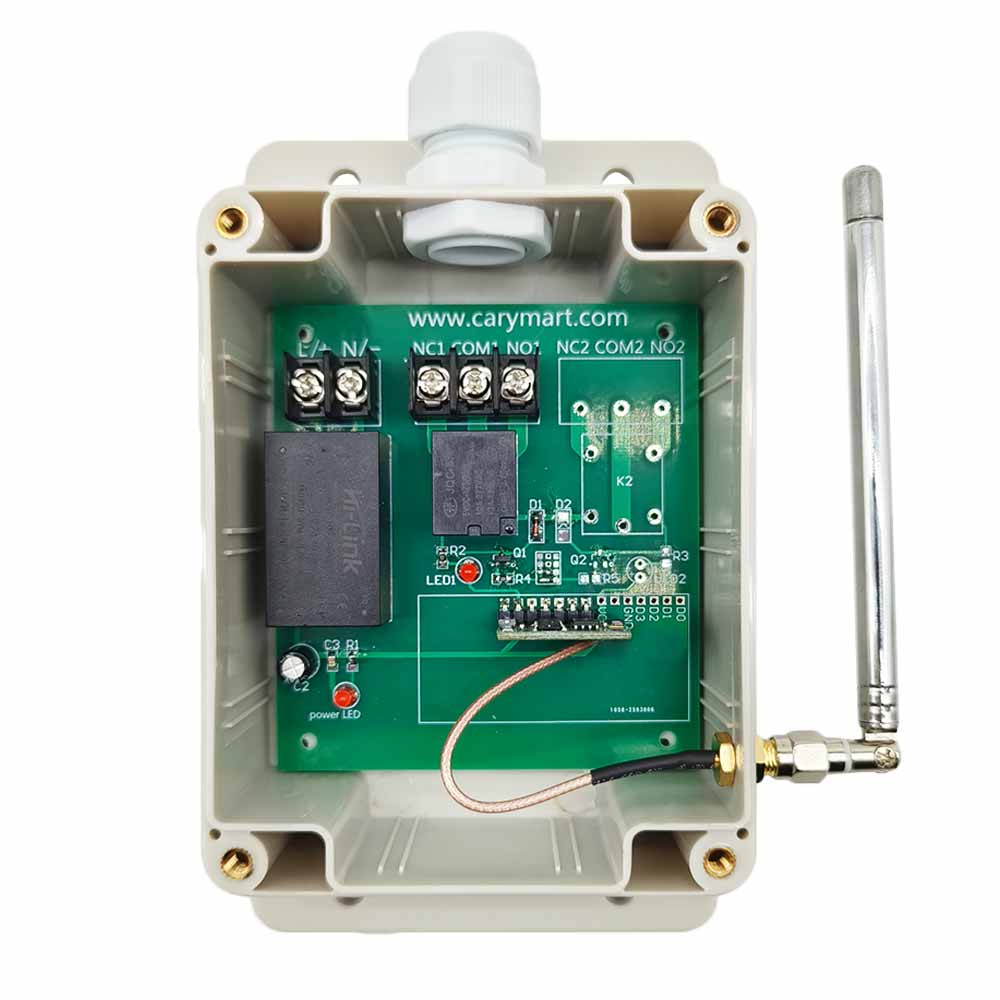
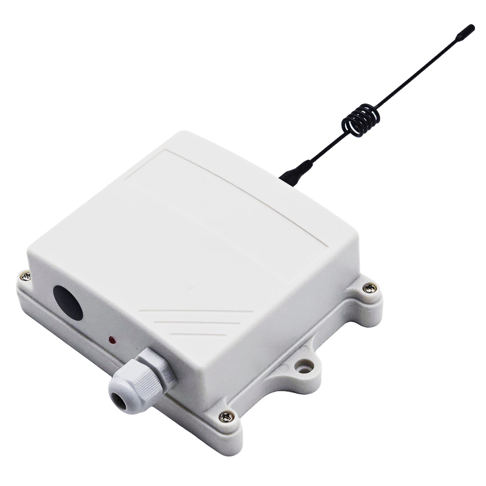
This receiver is an electric device with relay output, it and the
transmitter form a wireless remote-control system. This system may be used
in all types of industry automation, agriculture, business, home, factory,
house, farm, garage, vehicle, ship, aerial vehicle, etc. It can remote
control different DC or AC equipment on land, water, and air, such as
lights, doors, windows, lamps, sockets, locks, sirens, outlets, heaters,
motors, fans, electric solenoid valves, and security alarm systems. The
applications are endless.
Feature:
Wireless control, easy to install.
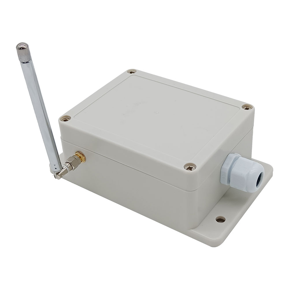
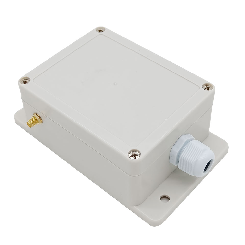
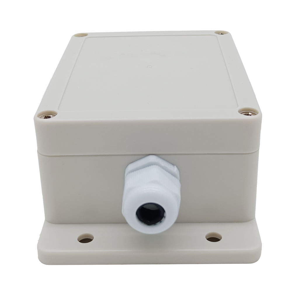
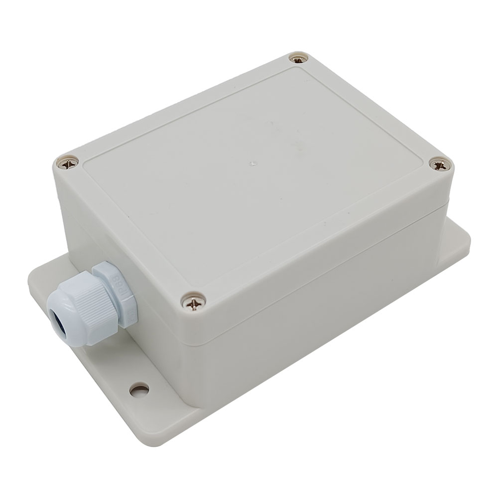
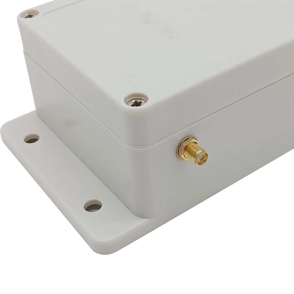
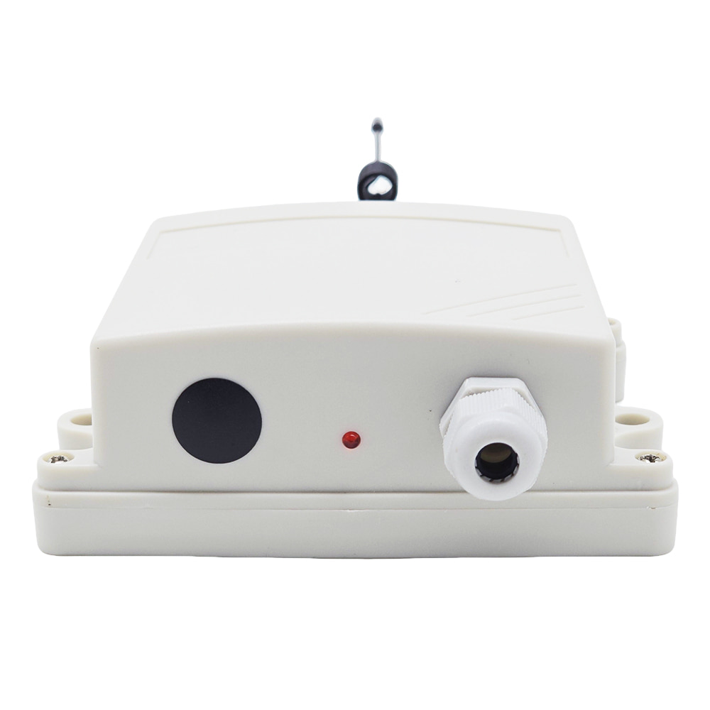
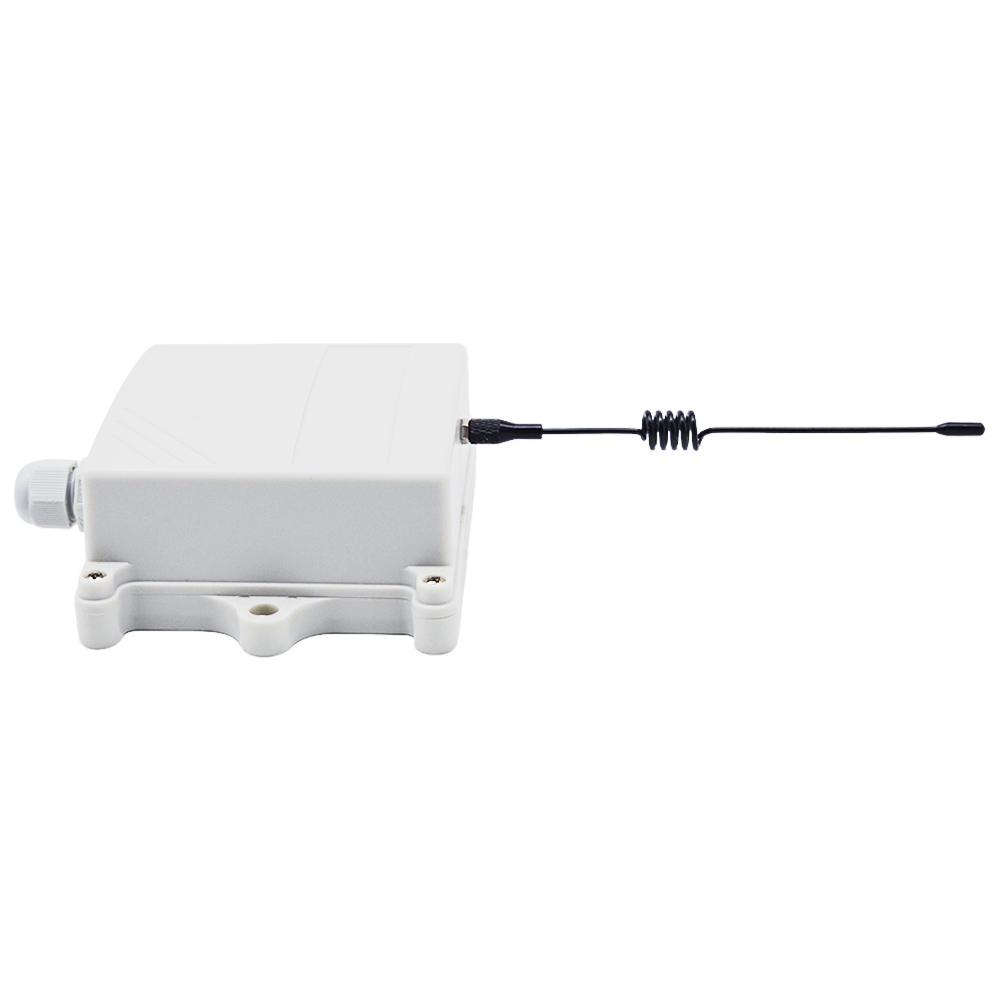
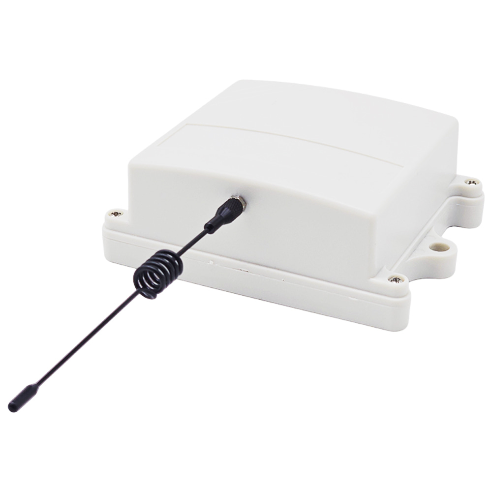
Waterproof: The receiver has waterproof case and waterproof connector, it
can be installed outdoors.
Universal input: Support 110V AC (110V~120V) used in US, Canada, etc, and
220V AC (220V~240V) used in Germany, UK, France, etc.
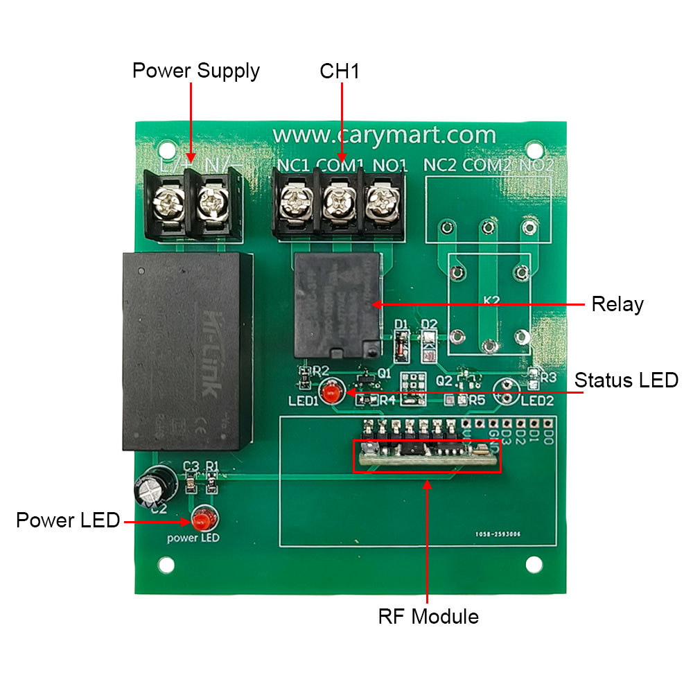
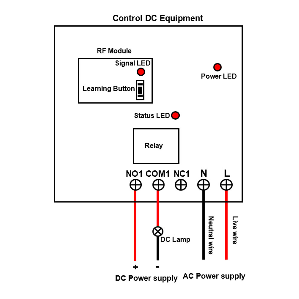
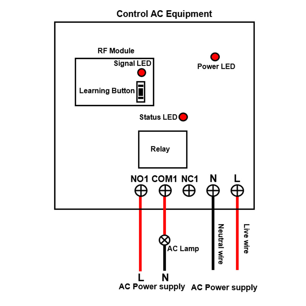
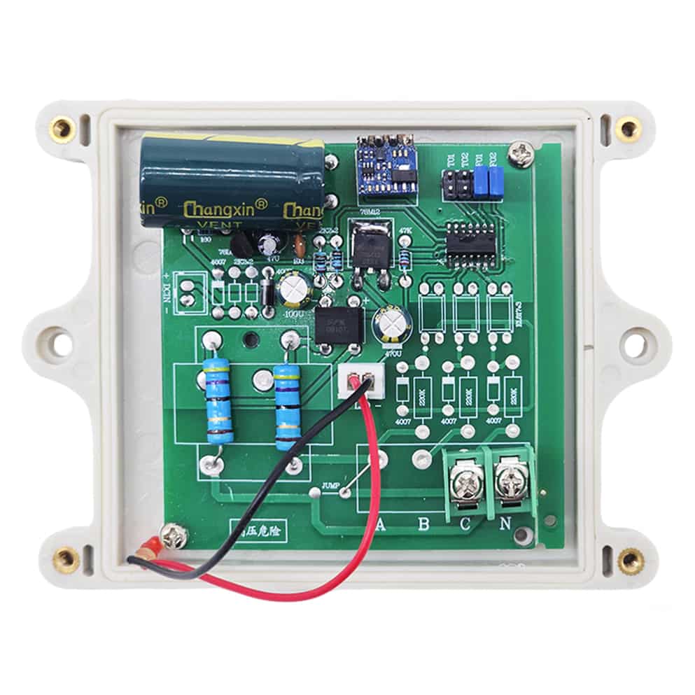
Relay Output: This receiver is dry relay output; it can be used to operate
both DC and AC equipment. The output terminals are NO / NC (normally open /
normally closed), serving as a switch. That means you should also connect a
separate power supply to equipment.
Each channel can work at maximum current 10A.
Working Mode: Interlocking (The receiver must be set to interlocking mode; momentary mode and self-locking mode are not suitable.)
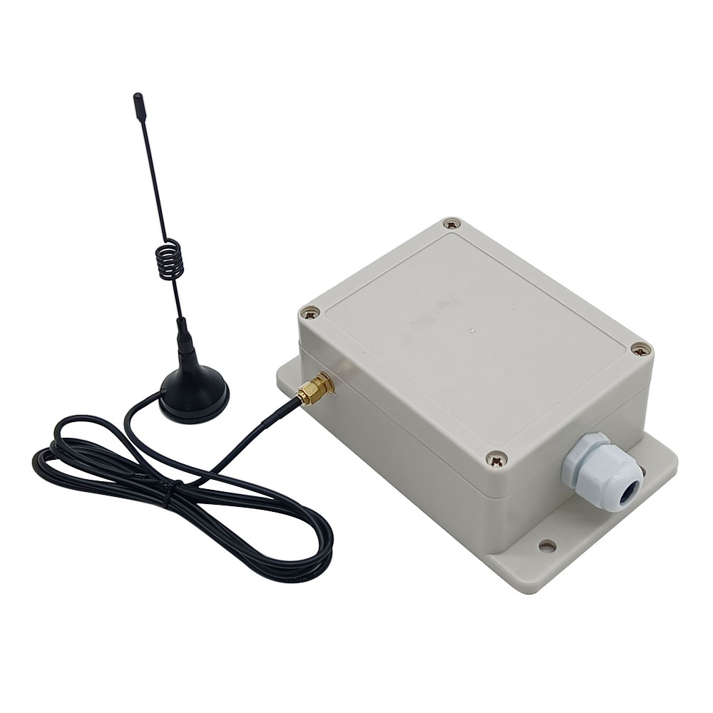
With external antenna, the receiver has a farther working range.
The transmitter / remote can control the receiver from any place within a
reliable working distance.
Wireless RF signal from the transmitter can pass through walls, floors,
doors, or windows, but it will lose some operating range.
The receiver has reverse voltage protection and overcurrent protection.
The receiver can only be triggered by paired transmitters.
Two or more receivers may be used in the same area.
Receiver Parameters:
Model: S1U-AC-ANT3
Operating Voltage: 110~240V AC (110V/120V/220V/240V)
Working Frequency: 433.92 MHz
Quiescent Current: ≤6mA
Channel: 1 CH
Output Type: Relay Output (With Normally Open and Normally Closed Terminals)
Maximum Load Voltage of Relay: 240VAC or 28VDC
Maximum Load Current of Relay: 10A / channel
Suitable Wires for Connecting Terminals: 22-12 AWG
Working Mode: Interlocking
Operating Temperature: -20 °C ~ +70 °C
PCB size: 88 x 80 x 18 mm (3.5 x 3.1 x 0.7 inches)
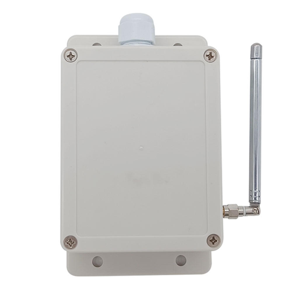
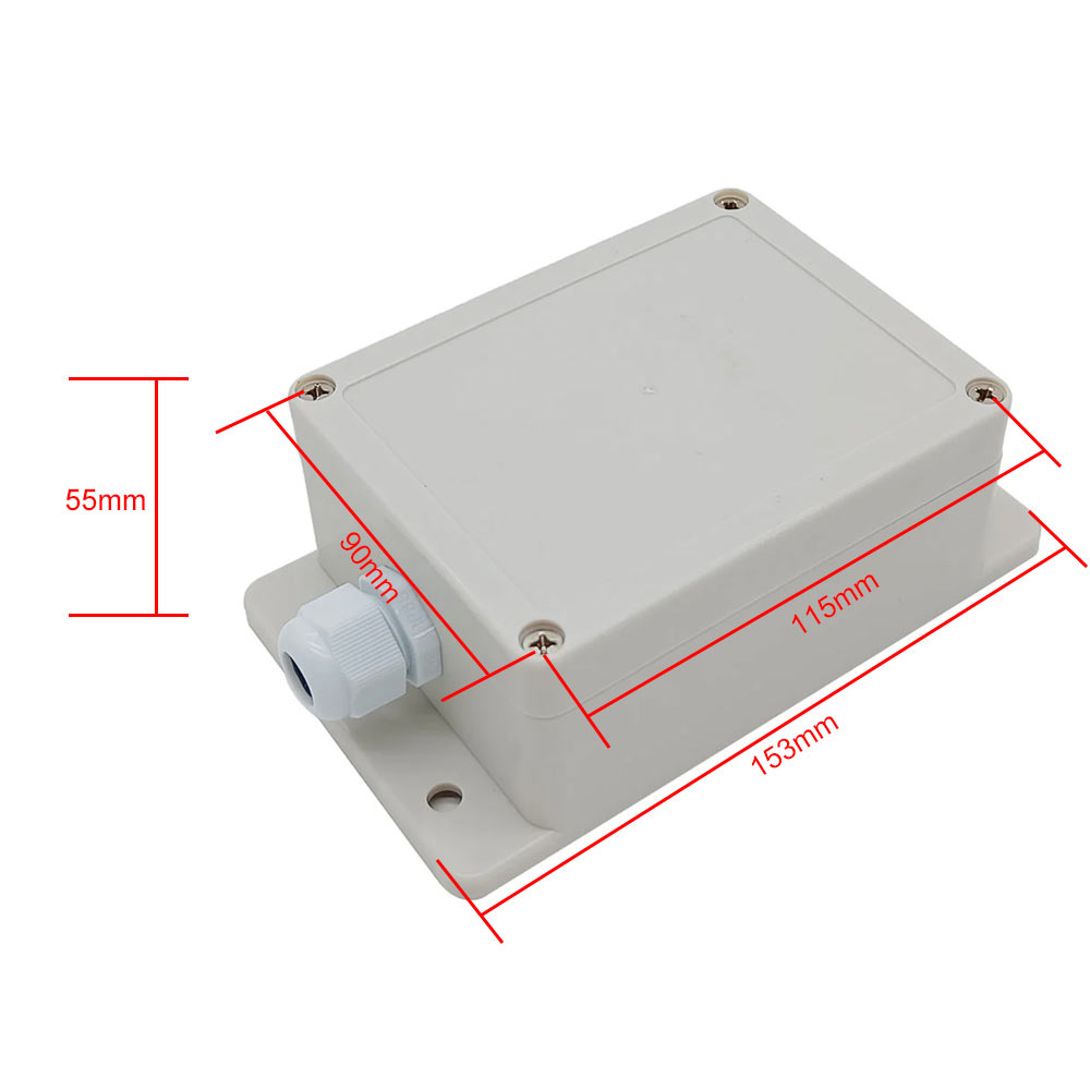
Case size: 153 x 90 x 55 mm (6.0 x 3.6 x 2.2 inches)
Transmitter Parameters:
Model: CK-DC
With 2 input wires, there is no need to distinguish between positive and
negative poles.
No batteries are required for operation.
Triggered by 12~24V DC voltage signal.
Triggering method: When the input wire gets the DC voltage signal, after 1
second, the signal LED on the transmitter flashes rapidly, the transmitter
sends a wireless signal "ON". After the transmission is completed, the
signal LED remains on. When the input wire loses the DC voltage signal,
after 1 second, the signal LED flashes rapidly, the transmitter sends a
wireless signal "OFF". After the transmission is completed, the signal LED
flashes once and then goes out.
Signal Transmission Time: 1 second
Operating Frequency: 433.92MHz (315MHz can be customized)
Encoding Chip: PT2262 / SC2262
Transmission Distance: 500m / 1500ft (theoretically)
PCB size: 73 x 73 x 19 mm (2.9 x 2.9 x 0.8 inches)
Case size: 110 x 86 x 40 mm (4.3 x 3.4 x 1.6 inches)
Working Range:
This receiver and transmitter CK-DC form a complete set, the maximum working distance may reach 1500 feet or 500 meters in an open area.
The maximum working distance is based on theoretical data without obstacles and any RF interference. In practice, it will be hindered by trees, walls, or other construction, and will be interfered with by other wireless signals. Therefore, the actual working distance may not reach this maximum distance.
Working Principle:
Transmitter CK-DC is a special remote control that is triggered by 12~24V DC
Power ON and OFF conditions. It has 2 input wires for connecting an DC
voltage signal from an equipment, such as outlet, warning host, detector,
sensor, Programmable Logic Controller, DC siren, DC light or other DC
equipment.
When an DC voltage is supplied to its input wires, it will transmit a
wireless signal "ON". When the input wires stop getting DC voltage, it will
transmit a wireless signal "OFF".
This transmitter can be combined with different types of receivers to form a
wireless control system, and this system is used to wirelessly control
another device via an DC voltage signal or an DC output signal from one
device.
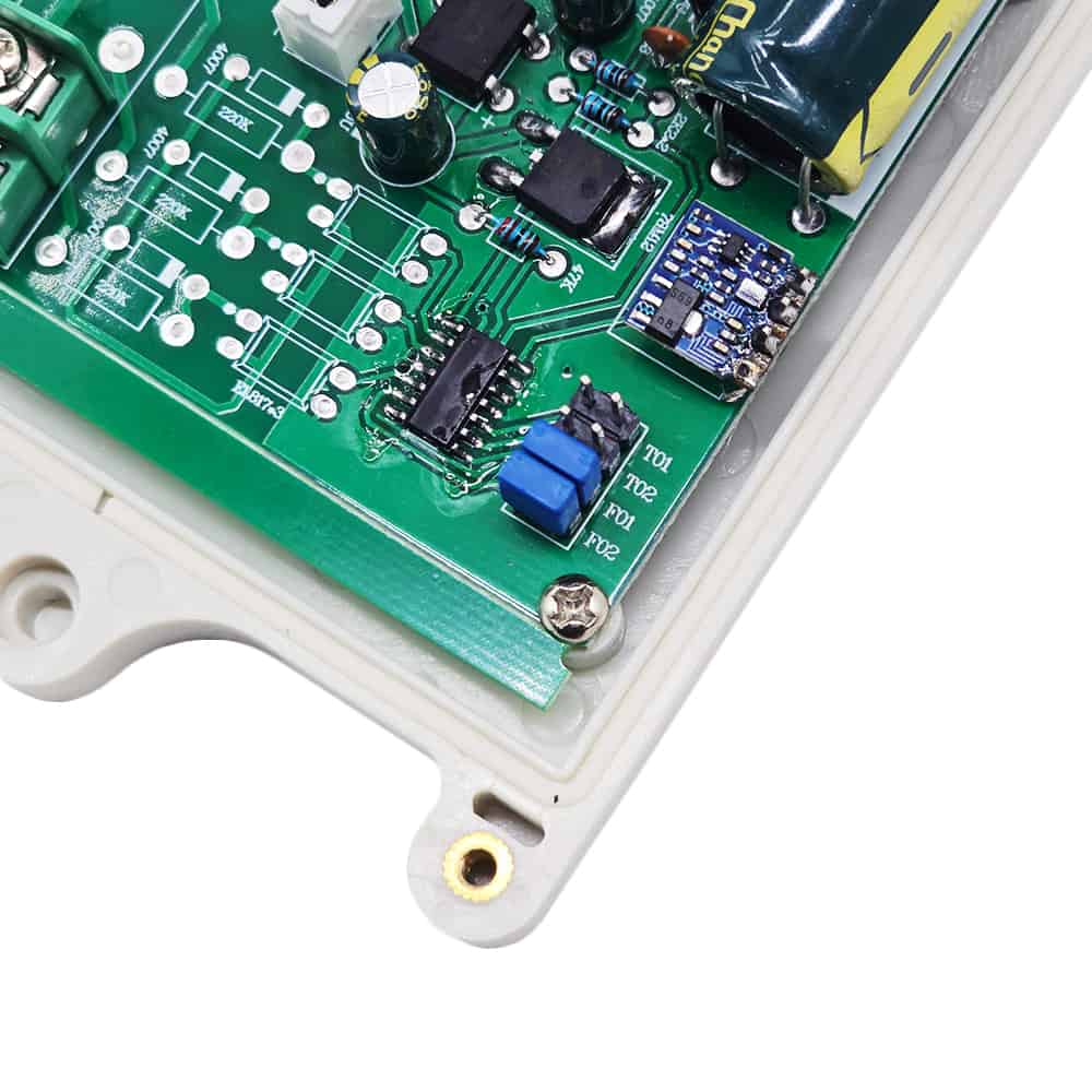
How to adjust the transmitter's oscillation resistance:
Short two pins of F02 with a jumper cap, the oscillator resistor is set to
1.5MΩ.
Do not short two pins of F01 and F02, the oscillator resistor is set to 2.2MΩ.
Short two pins of F01 with a jumper cap, the oscillator resistor is set to
3.3MΩ.
Short two pins of F01 and F02 with jumper caps respectively, the oscillator
resistor is set to 4.7MΩ.
Usage and operation:
If you want to control the device A by the 12V / 24V DC output signal of the
device B, do as following:
1. Connect the device A to the receiver's output terminal.
2. Connect the DC output terminal of device B to the input terminal of the
transmitter.
3. When device B outputs an DC signal to the transmitter, the transmitter
will emit a wireless signal "ON". When the receiver receives this wireless
signal, it will activate its relay to turn on the device A.
4. When device B stops outputting an DC signal to the transmitter, the
transmitter will emit a wireless signal "OFF". When the receiver receives
this wireless signal, it will deactivate its relay to turn off the device A.
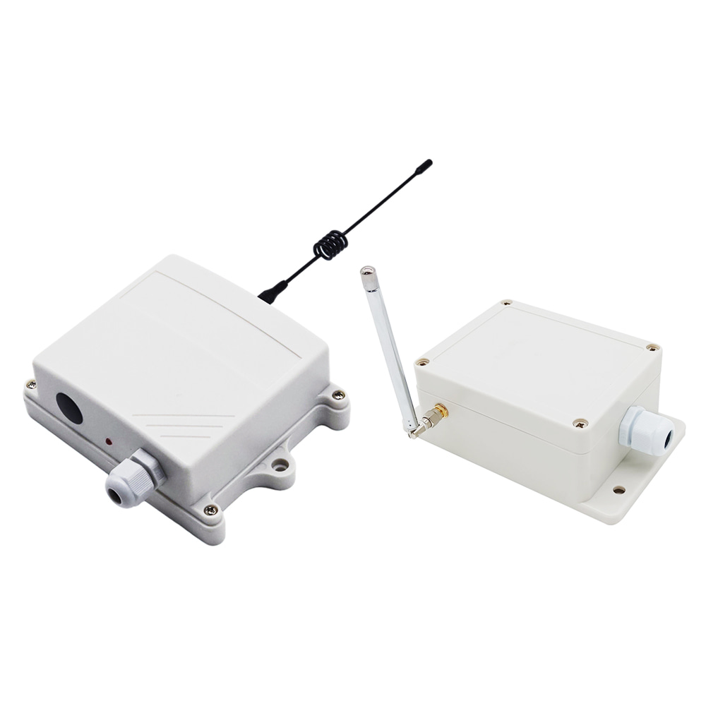
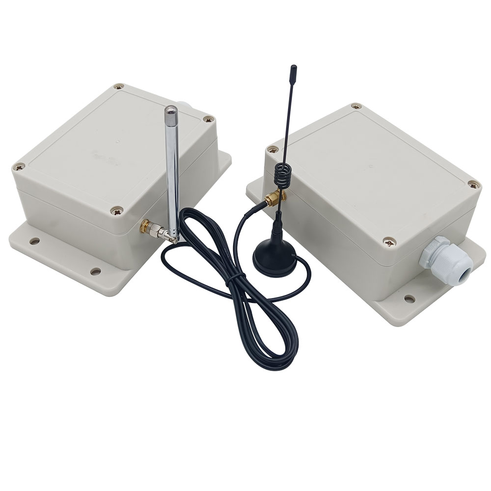
Package Include:
1 x Receiver: S1U-AC-ANT3
1 x Transmitter: CK-DC
1 x User manual