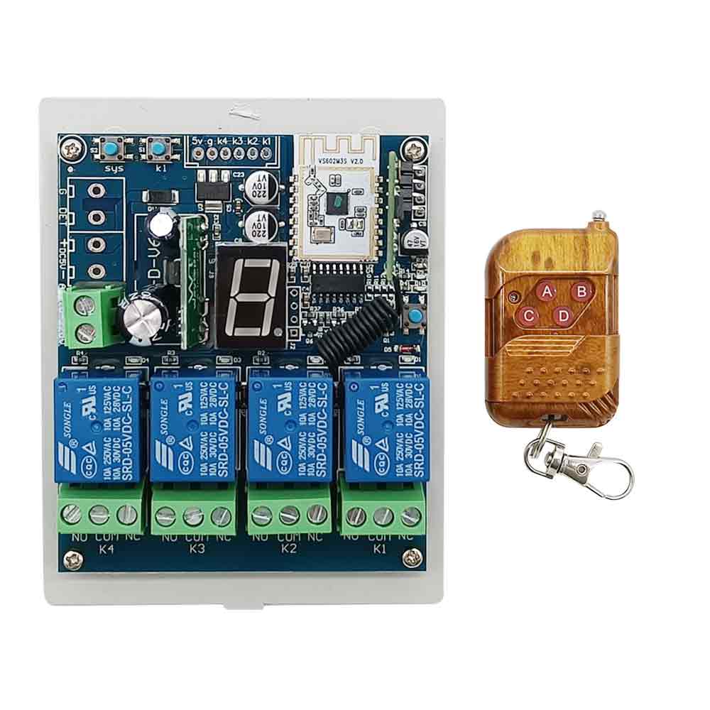
Package Include:
1 x WIFI Intelligent Switch
1 x Transmitter: C-4
1 x User manual
Application:
This WiFi switch is suitable for a variety of automation occasions, such as
industrial, agricultural, commercial, and home intelligence. Through
smartphones and the Internet, we use this WiFi switch to achieve remote
control of various devices. It has four dry relay outputs and can remote
control different AC or DC equipment on land, water, and air, such as
lights, doors, windows, lamps, sockets, locks, sirens, outlets, heaters,
motors, fans, winches, curtains, blinds, linear actuators, electric solenoid
valves, and security alarm systems. The applications are endless.
Feature:
Connect to the Internet via the WIFI signal of the wireless router.
Via smartphone app to control, no distance limit.
Relay Output: This switch is dry relay output; it can be used to operate
both DC and AC equipment. The output terminals are normally / open normally
closed, serving as a switch.
With working mode button: 12 different working modes can be switched.
With working mode display screen: Different numbers on the LED screen
correspond to different working modes.
With wired control terminals: You can connect manual switches or other
devices to control the WiFi switch.
With remote control function, you can use the remote to achieve control.
With Bluetooth function, you can use your mobile phone to control via
Bluetooth.
It can be operated by mobile phone and the remote at the same time.
It offers APP for Android or iOS, and APP is free to use.
The Android version of the app supports a variety of Android phones or
tablets.
The iOS version of the app supports a variety of iPhone, iPad and iPod
Touch.
The APP supports English, French, German, Spanish, Russian and other
languages.
Timing function: You can set the device to run automatically at different
times of the day.
Support for custom scene settings, can get out of the phone to achieve
automatic control.
With the sharing function, you can share this device with other mobile
phones for common operation.
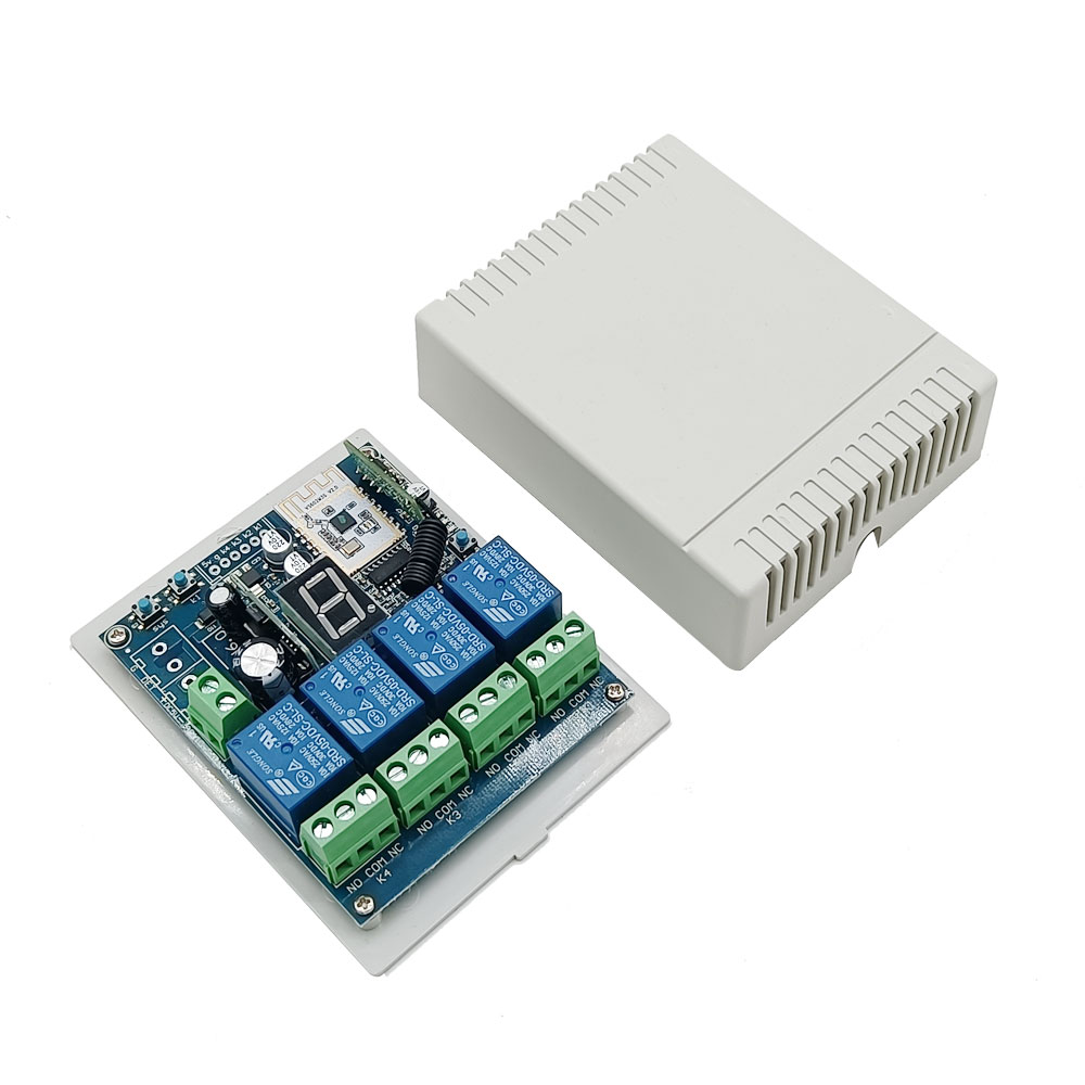
WIFI Switch Parameters:
Operating Voltage: DC 7~30V
Output Type: Dry Relay Output (With Normally Open and Normally Closed
Terminals)
Working Voltage Range of Relay: AC 110~240V or DC 0~28V
Suitable Wires for Connecting Terminals: 22-12 AWG
Channel: 4 CH
12 Selectable Working Modes: Self-locking, Momentary, Interlocking, Mixed
modes
Static Current: ≤6mA
Operating Temperature: -20°C ~ +70°C
Maximum Load Current of Relay: 7A / channel
PCB size: 94 x 73 x 21mm (3.7 x 2.9 x 0.8 inches)
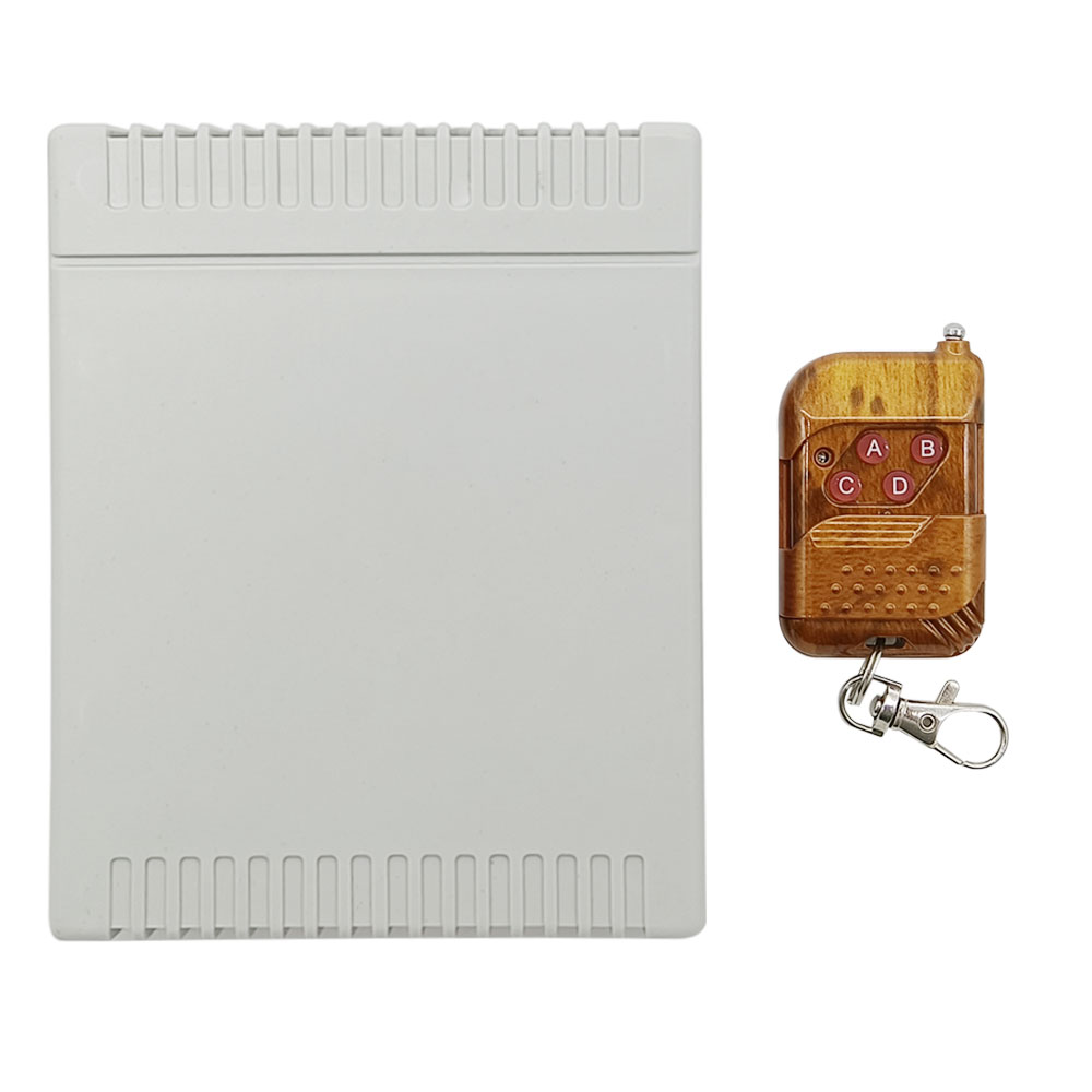
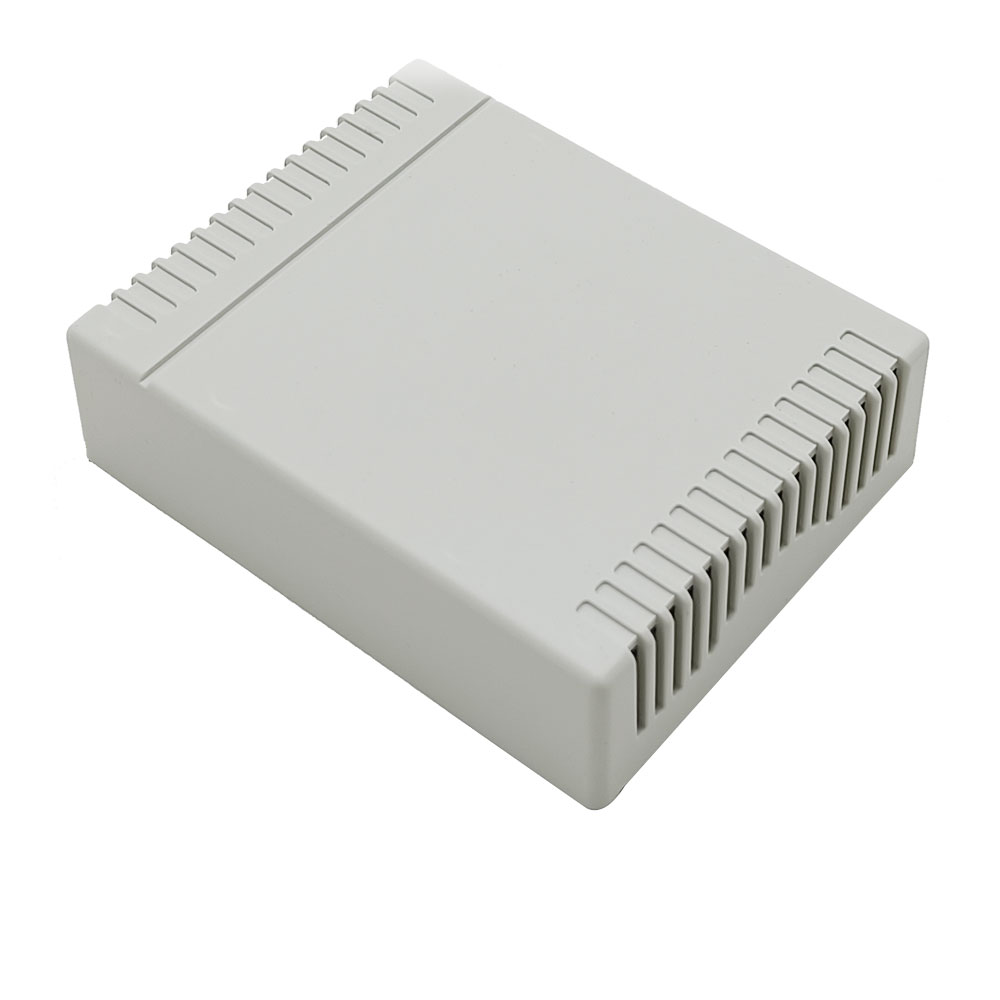
Case size: 100 x 80 x 28mm (3.9 x 3.2 x 1.1 inches)
Transmitter Parameters:
Model: 0021003 (C-4)
With Sliding Cover: Slide up when it doesn’t work (to protect the button).
Slide down the button will appear.
Channel/Button: 4
Button Symbol: 1, 2, 3, 4
Operating Voltage: 12V (1 x 23A -12V battery, can be used for 12 months)
Operating Current: 6mA
Operating Frequency: 433Mhz
Encoding Chip: PT2262 / PT2264 / SC2262
Encoding Type: Fixed code by soldering, up to 6561 codes
Transmitting Distance: 100m / 300ft (theoretically)
Modulation Mode: ASK
Unit Size: 58 x 39 x 16mm (2.3 x 1.5 x 0.6 inches)
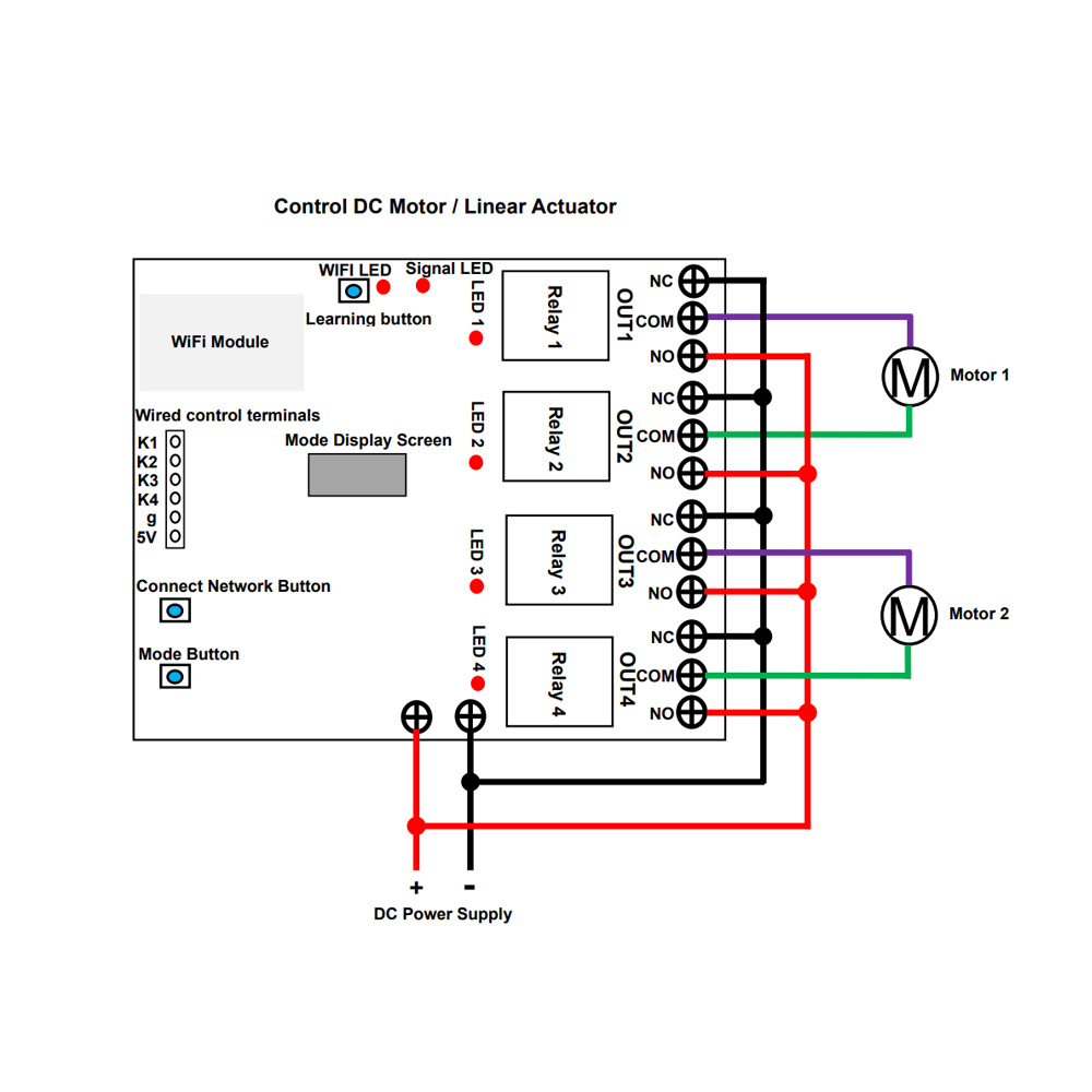
Wiring for DC motor or linear actuator:
If you want to control DC linear actuator or small bi-directional DC motor
(two control lines), do as following:
Please refer to the connection diagram below, and each two relays can be
connected to a DC motor or linear actuator, so 4 relays can be used to
connect two DC motors or linear actuators.
1. Connect the positive pole of DC power supply to the terminal + of the WiFi switch, and connect the negative pole of DC power supply to the
terminal - of the WiFi switch.
2. Connect the positive pole of the DC power supply to the terminal NO of
each two relays, and connect the negative pole of the DC power supply to the
terminals NC of each two relays.
3. Connect two wires of DC motor or linear actuator to the terminal COM of
each two relays, and you can exchange these two wires to change the rotating
direction of motor or the moving direction of linear actuator.
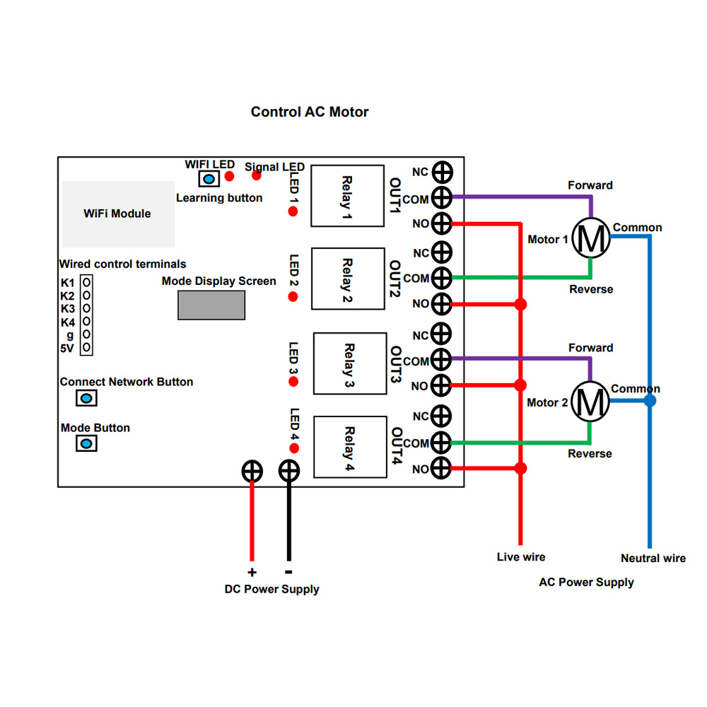
Wiring for AC motor:
If you want to control small bi-directional AC motor (three control lines),
do as following:
Please refer to the connection diagram below, and each two relays can be
connected to an AC motor, so 4 relays can be used to connect two AC motors.
1. Connect the positive pole of DC power supply to the terminal + of the WiFi
switch, and connect the negative pole of DC power supply to the terminal - of the WiFi switch.
2. Connect the live wire of the AC power supply to the terminal NO of each
two relays, connect the neutral wire of the AC power supply to the common
wire of the AC motor.
3. Connect the forward and reverse wires of the AC motor to the terminal
COM of each two relays, and you can exchange these two wires to change the
rotating direction of motor.
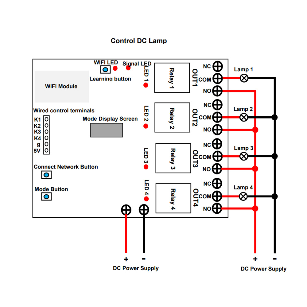
Wiring for DC lamp:
If you want to control DC lamp, do as following:
Please refer to the connection diagram below, and each relay can be
connected to a DC lamp, so 4 relays can be used to connect 4 lamps.
1. Connect the positive pole of DC power supply to the terminal + of the WiFi switch, and connect the negative pole of DC power supply to the
terminal - of the WiFi switch.
2. Connect the positive pole of the DC power supply to the terminal NO of
the relay, connect the terminal COM of the relay to the positive pole of
the DC lamp, and connect the negative pole of the DC lamp to the negative
pole of the DC power supply.
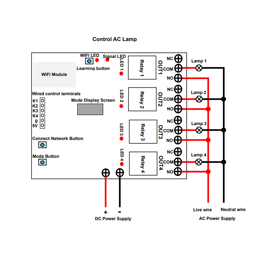
Wiring for AC lamp:
If you want to control AC lamp, do as following:
Please refer to the connection diagram below, and each relay can be
connected to an AC lamp, so 4 relays can be used to connect 4 lamps.
1. Connect the positive pole of DC power supply to the terminal + of the WiFi
switch, and connect the negative pole of DC power supply to the terminal - of the WiFi switch.
2. Connect the live wire of AC power supply to the terminal NO of the
relay, connect one side of AC lamp to the terminal COM of the relay, and
connect another side of AC lamp to the neutral wire of AC power supply.
How to set 12 different working modes:
Each time the mode button is pressed, the number on the LED screen
changes, and different numbers correspond to different working modes.
LED Screen display "1": Four channels are self-locking mode.
LED Screen display "2": Channel 1 is momentary mode, and the other three
channels are self-locking mode.
LED Screen display "3": Channels 1 and 2 are momentary mode, and channels 3
and 4 are self-locking mode.
LED Screen display "4": Channels 1, 2 and 3 are momentary mode, and channel
4 is self-locking mode.
LED Screen display "5": Four channels are momentary mode.
LED Screen display "6": Channels 1 and 2 are interlocking mode, and channels
3 and 4 are interlocking mode.
LED Screen display "7": Four channels are interlocking mode.
LED Screen display "8": Channels 1, 2 and 3 are interlocking mode, and
channel 4 is self-locking mode.
LED Screen display "9": Channels 1, 2 and 3 are interlocking mode, and
channel 4 is momentary mode.
LED Screen display "A": Channels 1 and 2 are interlocking mode, and channels
3 and 4 is momentary mode.
LED Screen display "B": Channels 1 and 2 are interlocking mode, and channels
3 and 4 are self-locking mode.
LED Screen display "C": Channels 1 and 2 are interlocking mode, channel 3 is
self-locking mode, and channel 4 is momentary mode.
Operation in different working modes:
Note: For APP’s installation, registration, and use, please refer to the
manual of the APP.
1. Self-locking mode:
1) The operation via the APP:
Press the button 1 on the APP, the relay 1 is activated, two terminals NO
and COM of Relay 1 are connected, two terminals NC and COM are disconnected.
Press the button 1 again: the relay 1 is deactivated, two terminals NO and
COM of Relay 1 are disconnected, two terminals NC and COM are connected.
Press the button 2 on the APP, the relay 2 is activated, two terminals NO
and COM of Relay 2 are connected, two terminals NC and COM are disconnected.
Press the button 2 again: the relay 2 is deactivated, two terminals NO and
COM of Relay 2 are disconnected, two terminals NC and COM are connected.
Press the button 3 on the APP, the relay 3 is activated, two terminals NO
and COM of Relay 3 are connected, two terminals NC and COM are disconnected.
Press the button 3 again: the relay 3 is deactivated, two terminals NO and
COM of Relay 3 are disconnected, two terminals NC and COM are connected.
Press the button 4 on the APP, the relay 4 is activated, two terminals NO
and COM of Relay 4 are connected, two terminals NC and COM are disconnected.
Press the button 4 again: the relay 4 is deactivated, two terminals NO and
COM of Relay 4 are disconnected, two terminals NC and COM are connected.
2) The operation via the transmitter:
Press the button A on the transmitter, the relay 1 is activated; Press the
button A again: the relay 1 is deactivated.
Press the button B on the transmitter, the relay 2 is activated; Press the
button B again: the relay 2 is deactivated.
Press the button C on the transmitter, the relay 3 is activated; Press the
button C again: the relay 3 is deactivated.
Press the button D on the transmitter, the relay 4 is activated; Press the
button D again: the relay 4 is deactivated.
2. Momentary mode:
Note: For the channel in non-momentary mode, its operating time can be
set via the APP.
1) The operation via the APP:
Press and hold the button 1 on the APP, the relay 1 is activated, two
terminals NO and COM of Relay 1 are connected, two terminals NC and COM are
disconnected.
Release the button: The relay 1 is deactivated, two terminals NO and COM of
Relay 1 are disconnected, two terminals NC and COM are connected.
Press and hold 2 on the APP, the relay 2 is activated, two terminals NO and
COM of Relay 2 are connected, two terminals NC and COM are disconnected.
Release the button: The relay 2 is deactivated, two terminals NO and COM of
Relay 2 are disconnected, two terminals NC and COM are connected.
Press and hold the button 3 on the APP, the relay 3 is activated, two
terminals NO and COM of Relay 3 are connected, two terminals NC and COM are
disconnected.
Release the button: The relay 3 is deactivated, two terminals NO and COM of
Relay 3 are disconnected, two terminals NC and COM are connected.
Press and hold the button 4 on the APP, the relay 4 is activated, two
terminals NO and COM of Relay 4 are connected, two terminals NC and COM are
disconnected.
Release the button: The relay 4 is deactivated, two terminals NO and COM of
Relay 4 are disconnected, two terminals NC and COM are connected.
2) The operation via the transmitter:
Press and hold the button A on the transmitter, the relay 1 is activated;
Release the button: The relay 1 is deactivated.
Press and hold the button B on the transmitter, the relay 2 is activated;
Release the button: The relay 2 is deactivated.
Press and hold the button C on the transmitter, the relay 3 is activated;
Release the button: The relay 3 is deactivated.
Press and hold the button D on the transmitter, the relay 4 is activated;
Release the button: The relay 4 is deactivated.
3. Interlocking mode:
Note: The interlocking mode set via the mode button can be used to
control DC motor. Only the interlocking mode set by the APP can be used to
control 3-wire AC motor.
1) For the interlocking mode set via the mode button:
1.1 The operation via the APP:
If relay 1 and 2 are in interlocking mode:
Press the button 1 on the APP, the relay 1 is activated.
Press the button 2 on the APP, the relay 2 is activated, and then the relay
1 is deactivated.
If 4 relays are in interlocking mode:
Press the button 1 on the APP, the relay 1 is activated.
Press the button 2 on the APP, the relay 2 is activated, and then the relay
1 is deactivated.
Press the button 3 on the APP, the relay 3 is activated, and then the relay
2 is deactivated.
Press the button 4 on the APP, the relay 4 is activated, and then the relay
3 is deactivated.
1.2 The operation via the transmitter:
If relay 1 and 2 are in interlocking mode:
Press the button A on the transmitter, the relay 1 is activated.
Press the button B on the transmitter, the relay 2 is activated, and then
the relay 1 is deactivated.
If 4 relays are in interlocking mode:
Press the button A on the transmitter, the relay 1 is activated.
Press the button B on the transmitter, the relay 2 is activated, and then
the relay 1 is deactivated.
Press the button C on the transmitter, the relay 3 is activated, and then
the relay 2 is deactivated.
Press the button D on the transmitter, the relay 4 is activated, and then
the relay 3 is deactivated.
2) For the interlocking mode set by the APP:
2.1 The operation via the APP:
If relay 1 and 2 are in interlocking mode:
Press the button 1 on the APP, the relay 1 is activated.
Press the button 2 on the APP, the relay 2 is activated, and the relay 1 is
deactivated at the same time.
If 4 relays are in interlocking mode:
Press the button 1 on the APP, the relay 1 is activated.
Press the button 2 on the APP, the relay 2 is activated, and the relay 1 is
deactivated at the same time.
Press the button 3 on the APP, the relay 3 is activated, and the relay 2 is
deactivated at the same time.
Press the button 4 on the APP, the relay 4 is activated, and the relay 3 is
deactivated at the same time.
2.2 The operation via the transmitter:
If relay 1 and 2 are in interlocking mode:
Press the button A on the transmitter, the relay 1 is activated.
Press the button B on the transmitter, the relay 2 is activated, and the
relay 1 is deactivated at the same time.
If 4 relays are in interlocking mode:
Press the button A on the transmitter, the relay 1 is activated.
Press the button B on the transmitter, the relay 2 is activated, and the
relay 1 is deactivated at the same time.
Press the button C on the transmitter, the relay 3 is activated, and the
relay 2 is deactivated at the same time.
Press the button D on the transmitter, the relay 4 is activated, and the
relay 3 is deactivated at the same time.
Wired control terminals:
The WiFi switch has wired control terminals, and you can connect external
devices, sensors, or manual switches to these terminals, then use them to
control the WiFi switch.
You can connect the manual switches (with NO/NC contact) to the terminals
K1, K2, K3, K4 and G, then use the manual switches to control the WiFi
switch.
When connect the terminals K1 and G by the manual switch, the relay 1 is
activated; When disconnect the terminals K1 and G by the manual switch, the
relay 1 is deactivated.
When connect the terminals K2 and G by the manual switch, the relay 2 is
activated; When disconnect the terminals K2 and G by the manual switch, the
relay 2 is deactivated.
When connect the terminals K3 and G by the manual switch, the relay 3 is
activated; When disconnect the terminals K3 and G by the manual switch, the
relay 3 is deactivated.
When connect the terminals K4 and G by the manual switch, the relay 4 is
activated; When disconnect the terminals K4 and G by the manual switch, the
relay 4 is deactivated.
How to pair the transmitter to the WIFI switch:
Notice: We have paired the transmitter to the WIFI switch before leaving the
factory.
1) Press the learning button in the WIFI switch for 1- 2 seconds; signal LED
on the WIFI switch turns on, this indicates that the WIFI switch enters the
learning status.
2) Press any one button on the transmitter, signal LED flashes twice; then
press the button on the transmitter again, signal LED turns off, this
indicates that the pairing is successful.
3) The WIFI switch can learn several transmitters with different codes.
How to delete all transmitters codes stored in the WIFI switch:
We have paired the transmitter to the WIFI switch, if you don’t want the
WIFI switch to work with the transmitter, you can delete all transmitters
codes stored in the WIFI switch.
Operation: Press and hold the learning button in the WIFI switch for 3-4
seconds then release the button, the signal LED lights up, then flashes
rapidly three times and then goes off, this indicates that all stored codes
have been deleted successfully.