

Qty:
Product Application:
It is suitable for a variety of automation occasions, such as industrial,
agricultural, commercial and home intelligence. We use this WIFI switch to
convert a manual control or remote control device into a smart device that is
controlled via smartphone and the Internet. Such as modified garage doors,
rolling gates, swing gates, sliding gates, automatic doors, barrier gates,
access control, small motors and other equipment. If your device is already
equipped with a remote control, we can also use this WiFi switch to directly
modify the remote control to achieve smartphone control.
Product Parameters:
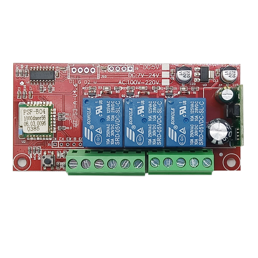
Working voltage: DC 7~30V
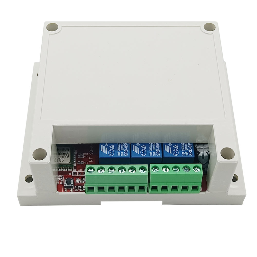
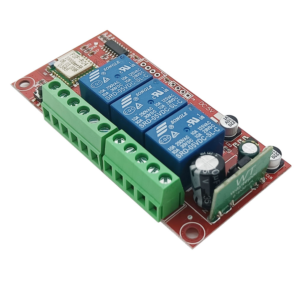
Output: relay output (normally open and normally close)
Relay working voltage range: AC 110~240V or DC 0~28V
The range of wires that the terminals can be connected: 22-12 AWG
Channel: 3 Channels
Working mode: Momentary
Static current: ≤6mA
Working temperature: -20°C ~ +70°C
Maximum load: 10A/channel
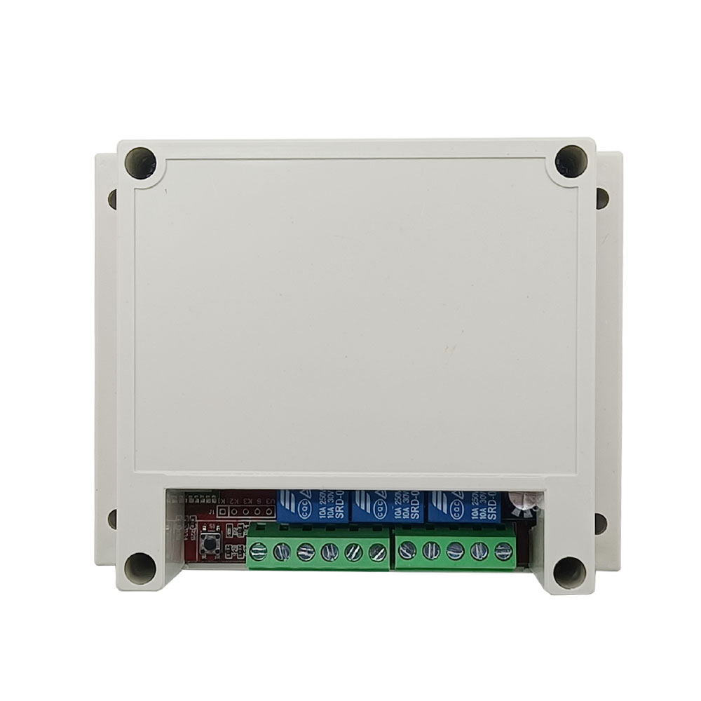
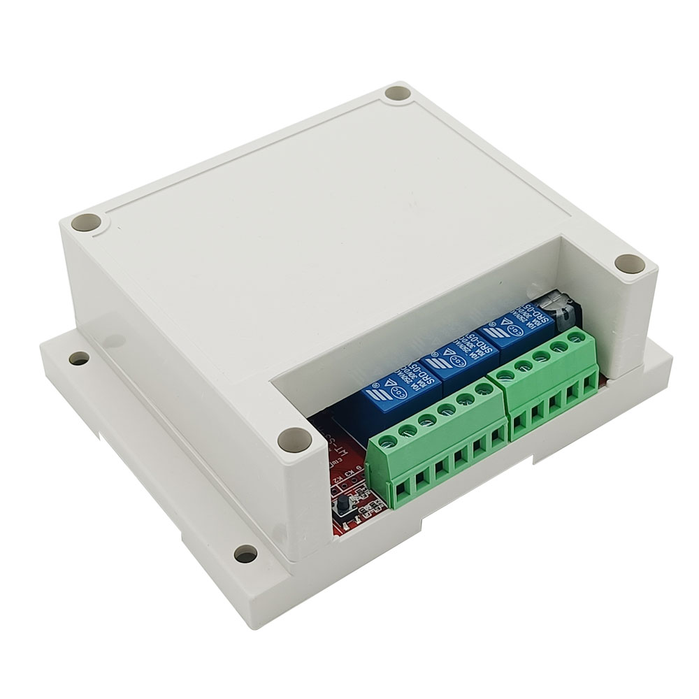
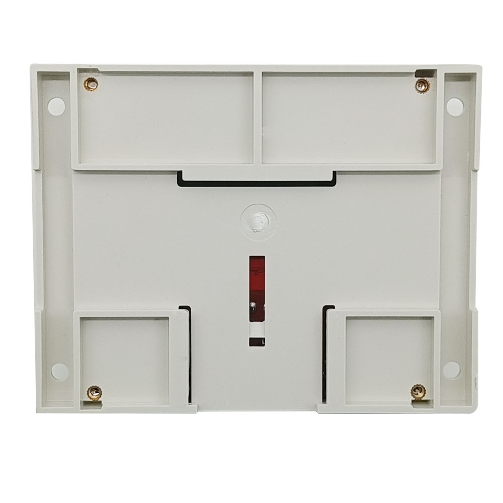
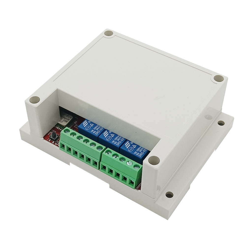
PCB size: 68mm x48mm x19mm
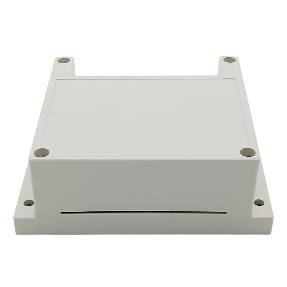
Shell size: 75mm x54mm x27mm
Product Features:
Connect to the Internet via the WIFI signal of the wireless router.
Via smartphone app to control, no distance limit.
Relay output: The output terminal is NO / NC and can be used to control DC or AC
equipment.
Manual switch port: Can be connected to manual switches or other devices to
control the WiFi switch.
Limited switch port: Can be connected to limit switches or other devices to
control the WiFi switch.
It has the characteristics of reverse power protection and overcurrent
protection.
It offers apps for Android and iOS and is free to use.
The Android version of the app supports a variety of Android phones or tablets.
The iOS version of the app supports a variety of iPhone, iPad and iPod Touch.
The APP supports English, French, German, Spanish, Russian and other languages.
Timing function: You can set the device to run automatically at different times
of the day.
Support for custom scene settings, can get out of the phone to achieve automatic
control.
With the sharing function, you can share this device with other mobile phones
for common operation.
Product Use:
A. For APP’s installation, registration and use, please refer to the manual of
the APP.
B. Modify various devices
1. Modify the access control button (with two control wires), connected as shown
below:
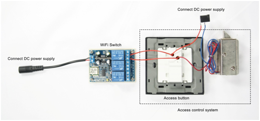
1) Connect the positive pole of the DC power supply to the input
terminal "+" of the WiFi switch, and connect the negative pole of the DC power
supply to the input terminal "-" of the WiFi switch;
2) Connect the two wires of the access button to the output terminals "NO" and
"COM" of the WiFi switch;
Operation:
Press button 1 on the APP, relay 1 is activated (two terminals "NO" and "COM" of
OUT1 are connected, two terminals "NC" and "COM" are disconnected), the
electronic control lock is opened; After 1 second, relay 1 is automatically
deactivated (two terminals "NO" and "COM" of OUT1 are disconnected, two
terminals "NC" and "COM" are connected), and the electronic control lock is
locked.
2. Modify the swing gate, sliding gate or automatic door, connect as shown
below:
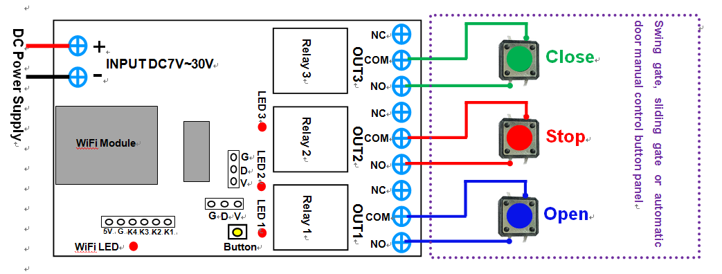
1) Connect the positive pole of the DC power supply to the input
terminal "+" of the WiFi switch, and connect the negative pole of the DC power
supply to the input terminal "-" of the WiFi switch;
2) Connect two pins of the manual control button "Open" of the electric door to
the first set of output terminals "NO" and "COM" of the WiFi switch;
3) Connect two pins of the manual control button "Stop" of the electric door to
the second set of output terminals "NO" and "COM" of the WiFi switch;
4) Connect two pins of the manual control button "Close" of the electric door to
the third set of output terminals "NO" and "COM" of the WiFi switch;
Control the automatic door through the smartphone APP, as follows:
1) Press the “UP” button on the APP, relay 1 is activated (two terminals
“OUT” and “COM” of OUT1 are connected, two terminals “NC” and “COM” are
disconnected), and the door is opened.
2) Press the button "DOWN" on the APP, relay 3 is activated (two terminals "NO"
and "COM" of OUT3 are connected, two terminals "NC" and "COM" are disconnected),
and the door is closed.
3) Press the button "STOP" on the APP, relay 2 is activated (two terminals "OUT"
and "COM" of OUT2 are connected, two terminals "NC" and "COM" are disconnected),
the door is stopped.
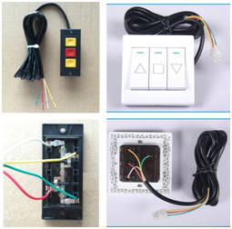
3. Modify garage doors or rolling gates:
The manual control buttons for garage doors or roller gates are as follows:
Modified connection diagram:
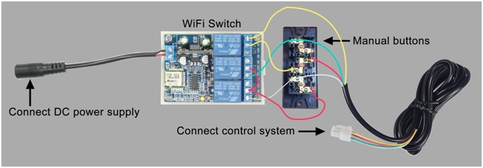
1) Connect the positive pole of the DC power supply to the input
terminal "+" of the WiFi switch, and connect the negative pole of the DC power
supply to the input terminal "-" of the WiFi switch.
2) Connect two wires from the terminal connected to the common wire (red wire)
on the manual button to two terminals "COM" of the "OUT1" and the "OUT2" of the
WiFi switch;
3) Connect a wire from the terminal connected to the opening wire (white wire)
on the manual button to the terminal "NO" of the "OUT1" of the WiFi switch;
4) Connect a wire from the terminal connected to the closing wire (green wire)
on the manual button to the terminal "NO" of the "OUT2" of the WiFi switch;
5) First remove the stop wire (yellow wire) from the manual button, and connect
this stop wire to the terminal "NC" of the "OUT3" of the WiFi switch, and then
connect a wire from the terminal connected to the stop wire on the manual button
to the terminal "COM" of the "OUT3" of the WiFi switch.
Control the garage door or the rolling gate through the smartphone APP, as
follows:
1) Press the “UP” button on the APP, relay 1 is activated (two terminals “OUT”
and “COM” of OUT1 are connected, two terminals “NC” and “COM” are disconnected),
and the door is opened.
2) Press the button "DOWN" on the APP, relay 2 is activated (two terminals "NO"
and "COM" of OUT2 are connected, two terminals "NC" and "COM" are disconnected),
and the door is closed.
3) Press the button "STOP" on the APP, relay 3 is activated (two terminals "NO"
and "COM" of OUT3 are connected, two terminals "NC" and "COM" are disconnected),
the door is stopped.
4. Modify the remote control and connect as shown
below:
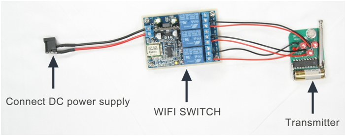
1) Connect the positive pole of the DC power supply to the input
terminal "+" of the WiFi switch, and connect the negative pole of the DC power
supply to the input terminal "-" of the WiFi switch;
2) Respectively connect a wire from the two unconnected pins of each button on
the remote control to the terminals "NO" and "COM" of each output of the WiFi
switch;
Control the remote control via the smartphone app, as follows:
Press the button "UP" on the APP, relay 1 is activated (two terminals "OUT" and
"COM" of OUT1 are connected, two terminals "NC" and "COM" are disconnected), and
the button "Open" on the remote control is triggered.
Press the button "DOWN" on the APP, relay 2 is activated (two terminals "NO" and
"COM" of OUT2 are connected, two terminals "NC" and "COM" are disconnected), and
the button "Close" on the remote control is triggered.
Press the button "STOP" on the APP, relay 3 is activated (two terminals "NO" and
"COM" of OUT3 are connected, two terminals "NC" and "COM" are disconnected), and
the button "Stop" on the remote control is triggered.
C. Manual control:
You can connect three two-pin momentary type manual switches respectively to
terminals "K1" and "G", "K2" and "G", "K3" and "G" to control these three
relays.
When use the momentary switch 1 to connect the terminals "K1" and "G", the relay
1 is activated, and the relay 1 is automatically deactivated after 1 second.
When use the momentary switch 2 to connect the terminals "K2" and "G", the relay
2 is activated, and the relay 2 is automatically deactivated after 1 second.
When use the momentary switch 3 to connect the terminals "K3" and "G", the relay
3 is activated, and the relay 3 is automatically deactivated after 1 second.
"eWeLink" APP Download, Registration and Login

Home | How To Buy | Specials | About Us | Sitemap | Contact Us | FAQs
Copyright @ 2012-2026 Remote Control System Store. Powered byCaryMart