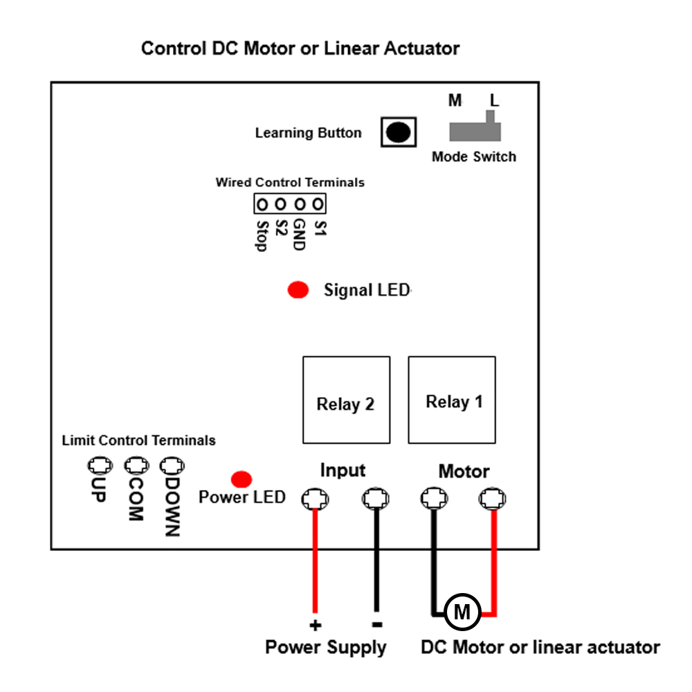
, and
you can exchange these two wires to change the rotating direction of motor
or the moving direction of linear actuator.
Setting Interlocking mode: Turn the mode switch in the receiver to
location L.
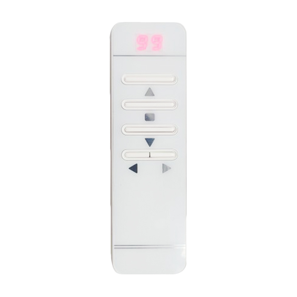
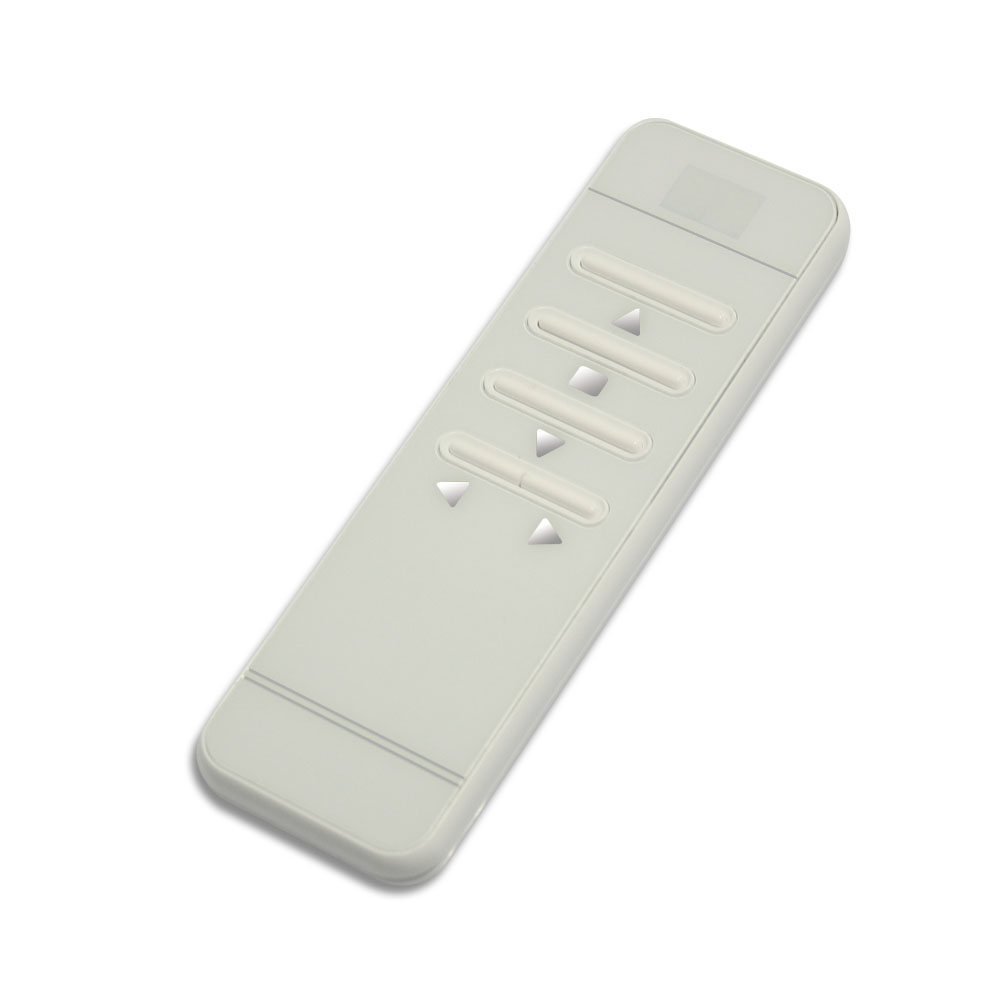
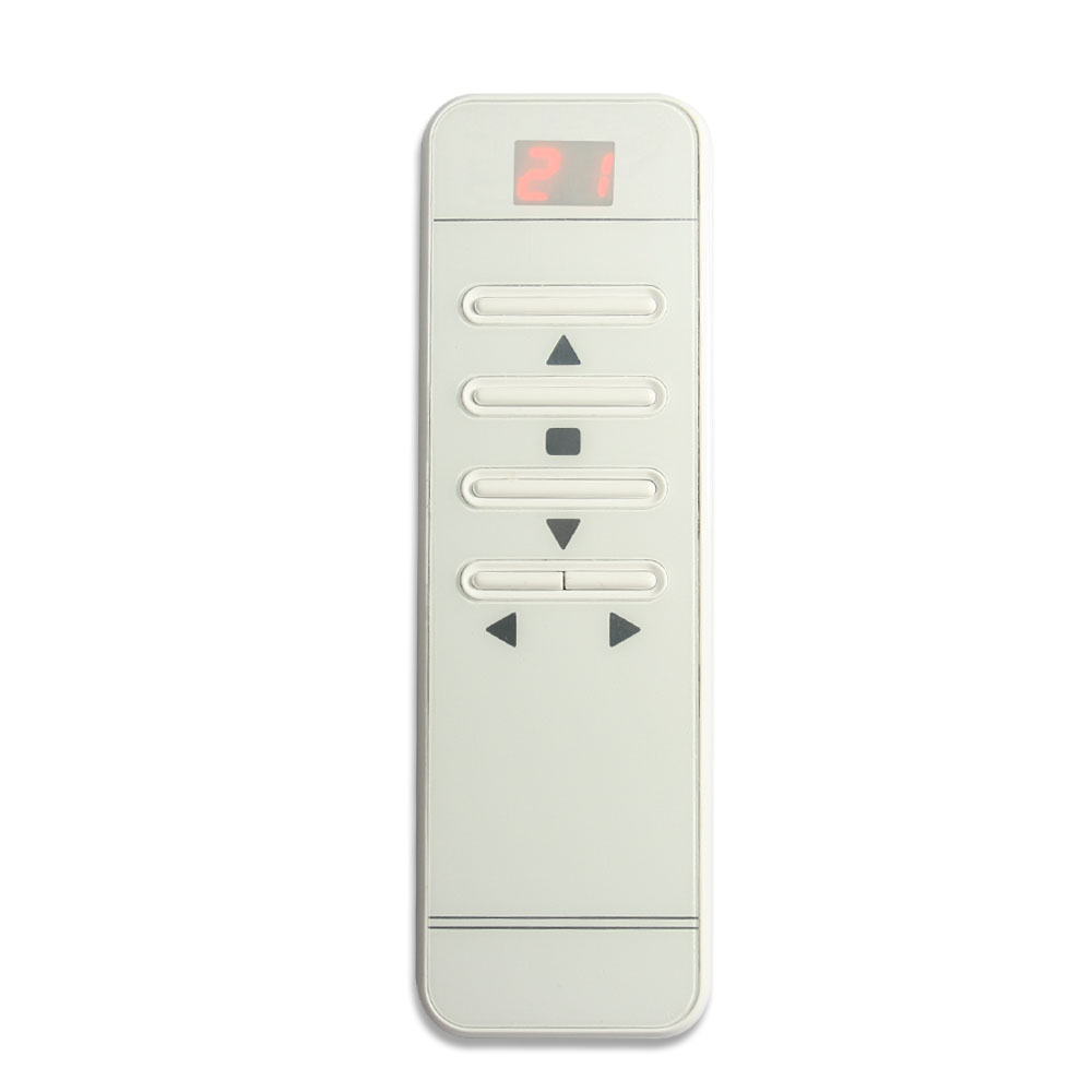
The operation by the transmitter, such as CM-99:
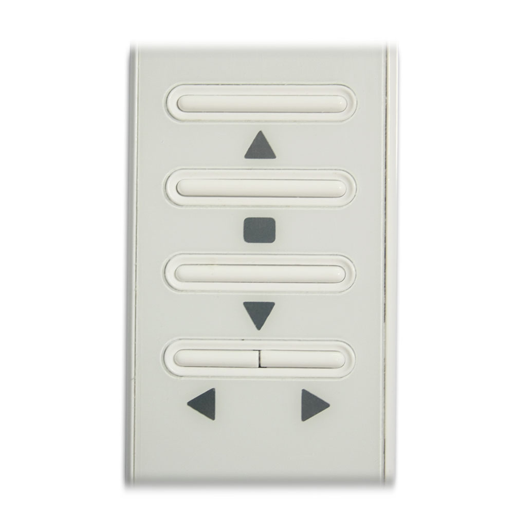
First press the button ◄ or ► on the transmitter to select the corresponding
channel, the digital screen will display the number of this channel, then
the screen automatically shut down after 2 seconds.
Press the button ▲ on the transmitter: Motor rotates in positive direction,
or linear actuator extends outward.
Press the button ▼ on the transmitter: Motor rotates in reversal direction,
or linear actuator inward retracts.
Press the button ■ on the transmitter: Motor or linear actuator stops.
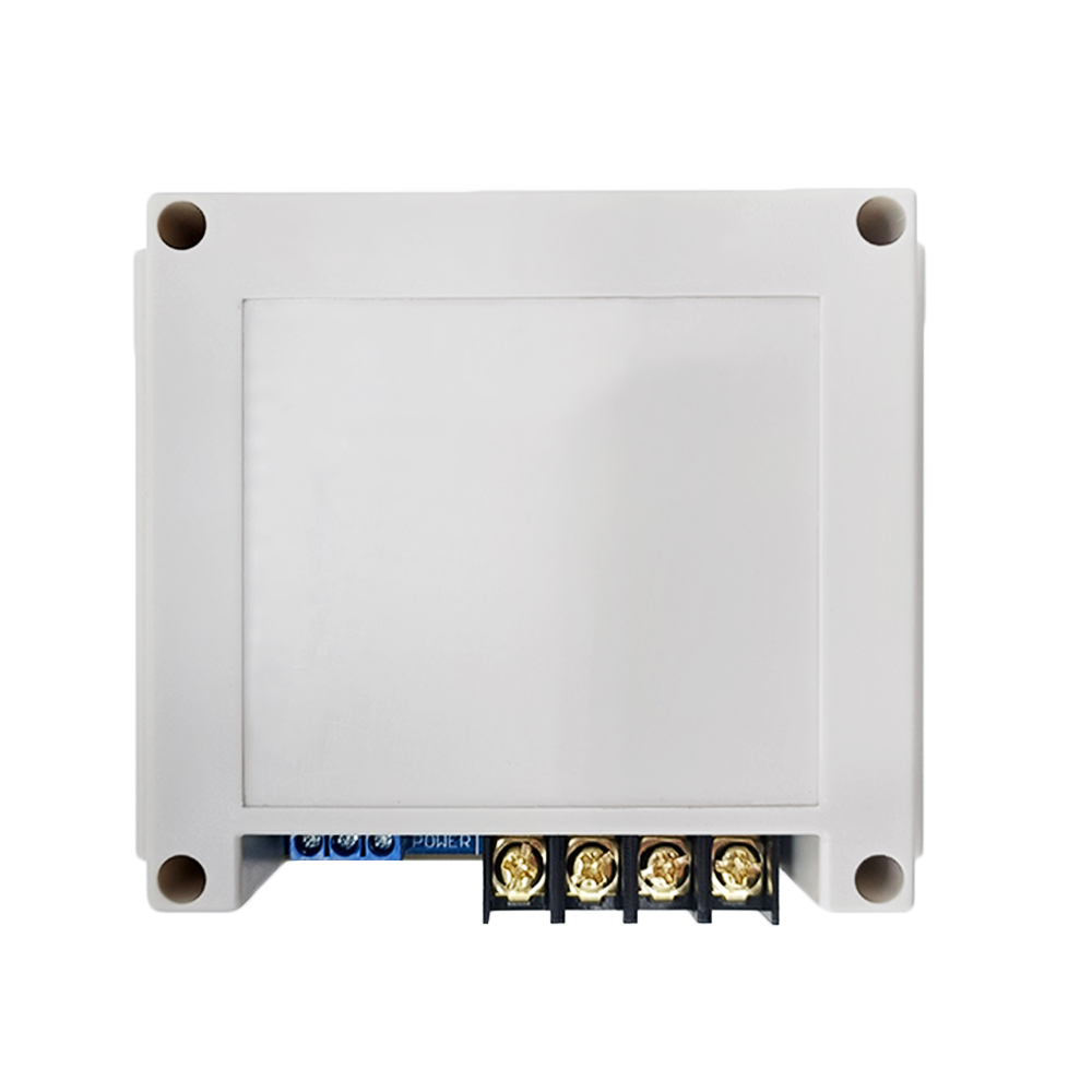
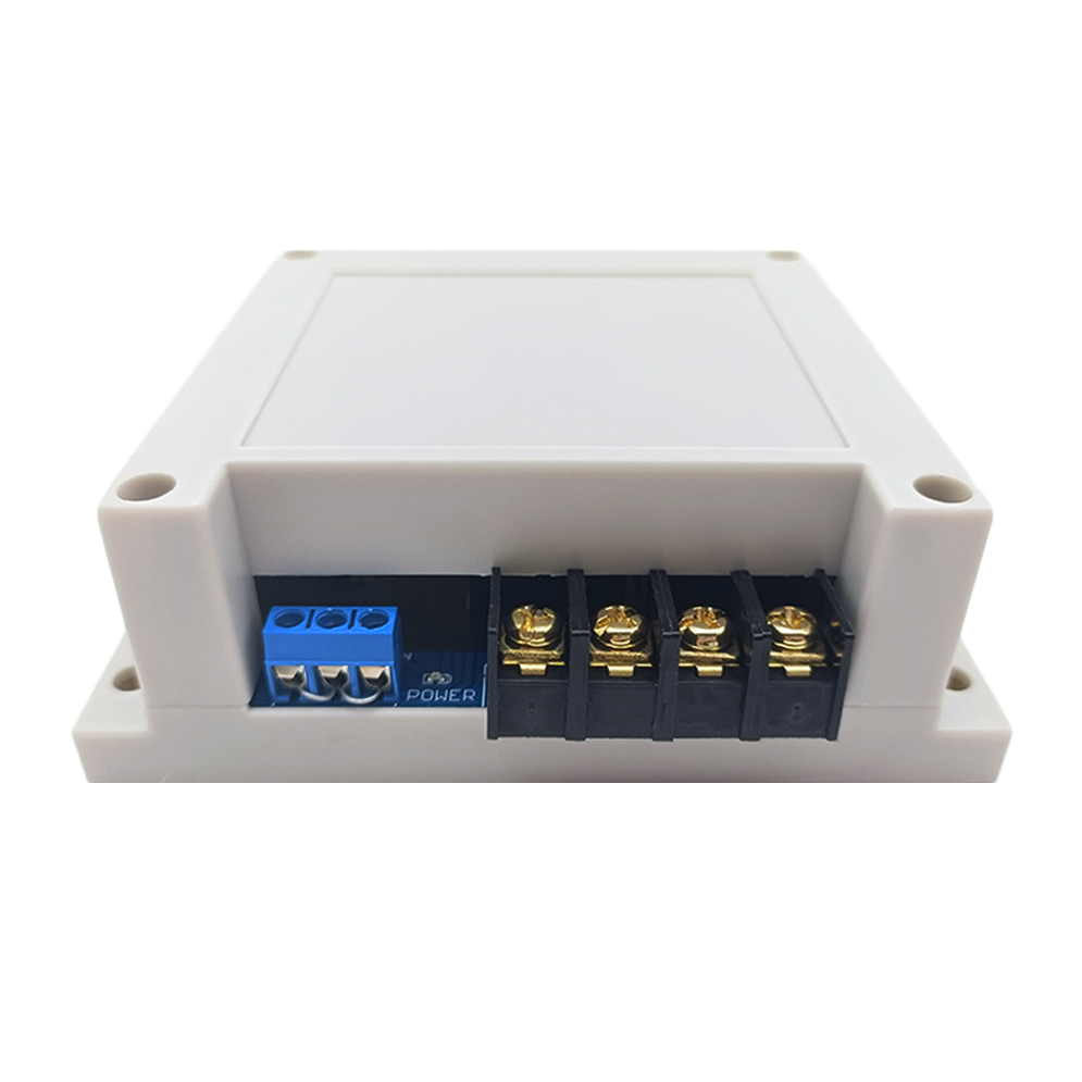
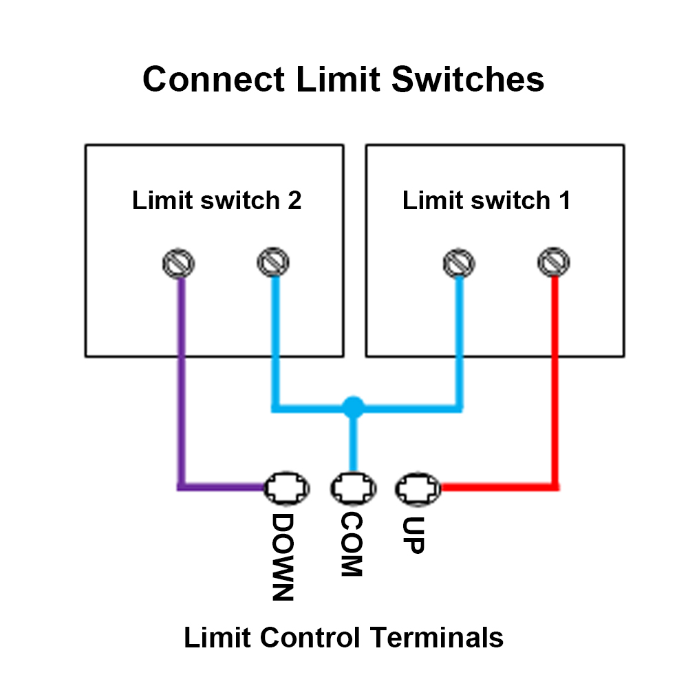
Limit control terminals:
The receiver has limit control terminals, and you can connect external devices (with normally closed contact), such as sensors, limit switches to limit terminals, then use them to stop the motor or the linear actuator.
For example, you can connect a normally closed limit switch to terminals COM and UP, and connect another normally closed limit switch to terminals COM and DOWN.
When motor rotates in positive direction, or linear actuator extends outward, if disconnect two terminals COM and UP, the motor or linear actuator will stop automatically.
When motor rotates in reversal direction, or linear actuator inward retracts, if disconnect two terminals COM and DOWN, the motor or linear actuator will stop automatically.
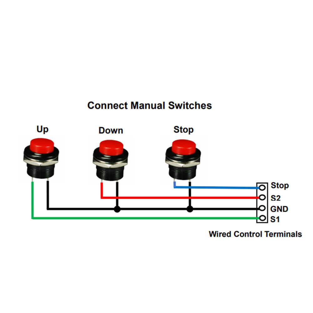
Wired control terminals:
The receiver has wired control terminals, and you can connect external devices (with normally open contact), such as manual switches to wired control terminals, then use them to stop the motor or the linear actuator.
For example, you can connect three button manual switches to wired control terminals STOP, S1, GND and S2 according to following wiring diagram.
For example, connect 3 pushbutton manual switch (Model 0040024):
When pressing the UP button, two terminals S1 and GND are connected, then the motor rotates in the positive direction, or the linear actuator extends outward. And when pressing the STOP button, two terminals STOP and GND are connected, then the motor or linear actuator stops.
When pressing the DOWN button, two terminals S2 and GND are connected, then the motor rotates reversal direction, or the linear actuator inward retracts. And when pressing the STOP button, two terminals STOP and GND are connected, then the motor or linear actuator stops.
How to pair the transmitter to the receiver:
You can pair any channel on the transmitter to any receiver you want to
control.
1) First press the button ◄ or ► on the transmitter to select the
corresponding channel, the digital screen will display the number of this
channel, then the screen automatically shut down after 2 seconds.
2) Select the receiver you want to control, then press the learning button
in the receiver for 1- 2 seconds; signal LED on the receiver turns on, this
indicates that the receiver enters the learning status.
3) Press the button ▲ on the transmitter, signal LED flashes twice; then
press the button ▼ on the transmitter, signal LED flashes twice; then press
the button ■ on the transmitter, signal LED flashes twice; finally press the
learning button in the receiver, signal LED turns off, this indicates that
the pairing is successful.
4) Press the learning button of receiver again for 1-2 seconds, the LED
signal turns off, it means the receiver exits the learning state.
How to delete all transmitters codes stored in the receiver:
We have paired the transmitter to the receiver, if you don’t want the
receiver to work with the transmitter, you can delete all transmitters codes
stored in the receiver.
Operation: Press and hold the learning button in the receiver for 4-5
seconds until signal LED flashes 3 times and then turns off, this indicates
all stored codes have been deleted successfully.
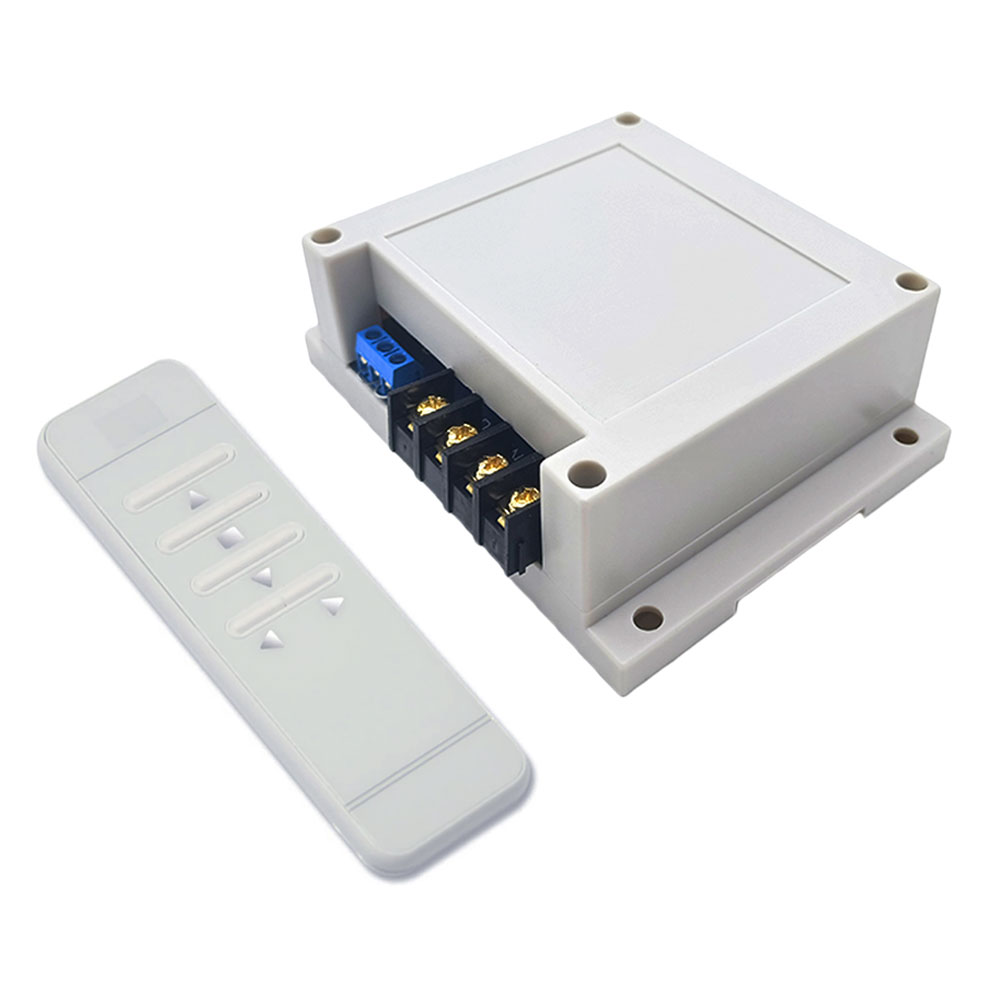
Package Include:
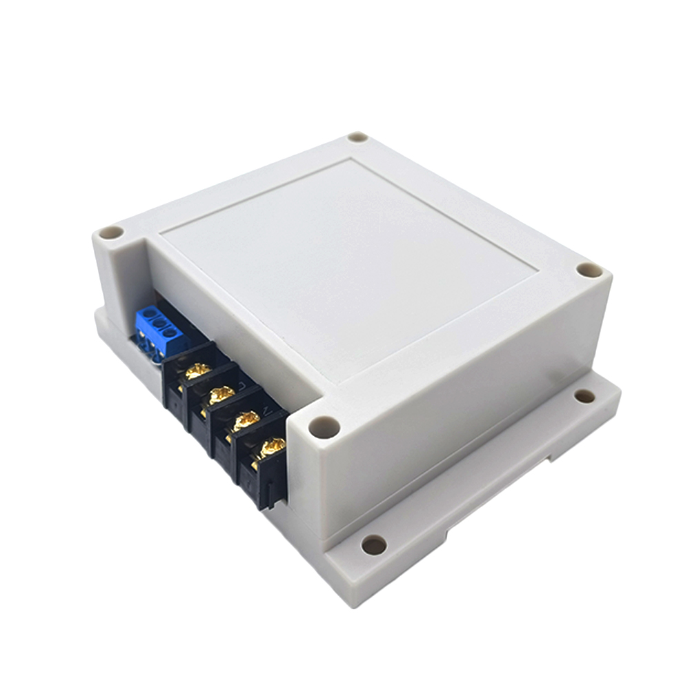
1 x Receiver: S1PF-DC12 / S1PF-DC24
1 x Transmitter: CM-99
1 x User manual