Hi, I'm Tom. Welcome to our shop,
Carymart offers you the premium rf remote control equipment.
We suggest you reading our FAQs before making your decision.
If you have any other question, please contact us.
We will reply you as soon as possible.
Application:
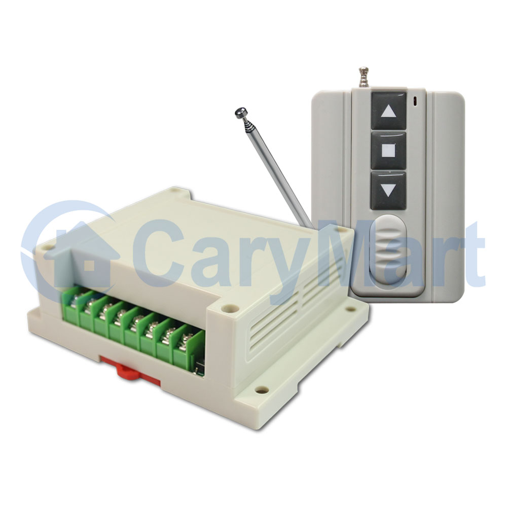
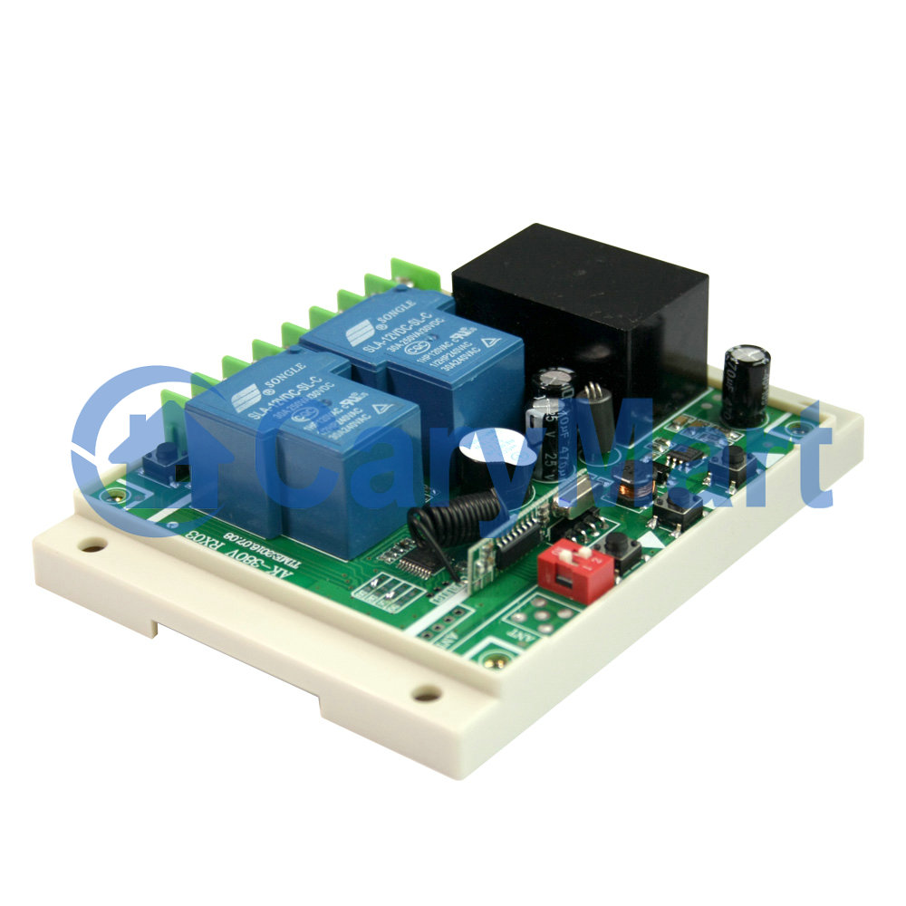
This receiver is an electric device with 2 relay outputs, it and the
transmitter form a wireless transmitter receiver system. This system may be
used in all types of industry automation, agriculture, business, home,
factory, house, farm, garage, vehicle, ship, aerial vehicle, etc. It can
remote control different DC or AC equipment on land, water, and air, such as
lights, doors, windows, lamps, sockets, locks, sirens, outlets, heaters,
motors, fans, winches, curtains, blinds, linear actuators, electric solenoid
valves, and security alarm systems. The applications are endless.
Feature:
Wireless control, easy to install.
Universal Power Supply: AC 100~450V, support AC 110V, AC 120V, AC220V, AC
240V, AC 380V.
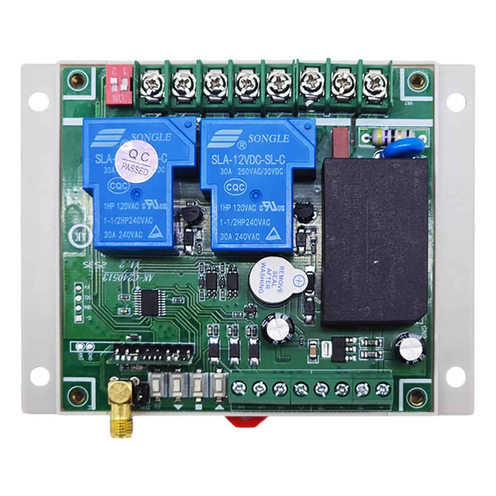
Relay Output: This receiver is relay output, it can be used to operate both
DC and AC equipment. The terminals are NO / NC (normally open / normally
closed), which serves as a switch. That means you should also connect a
separate power supply to equipment.
High Power: Each channel can work at maximum current 30A.
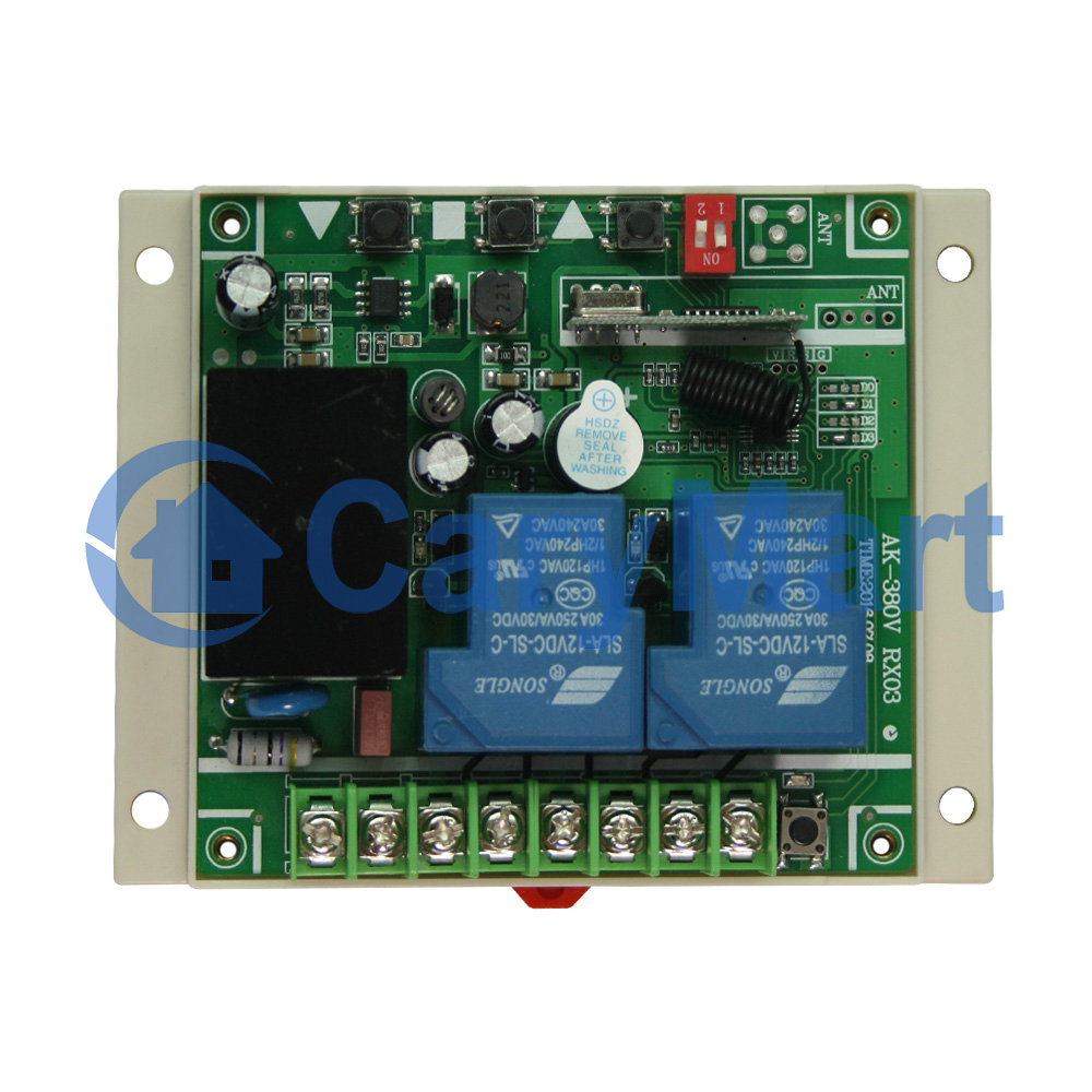
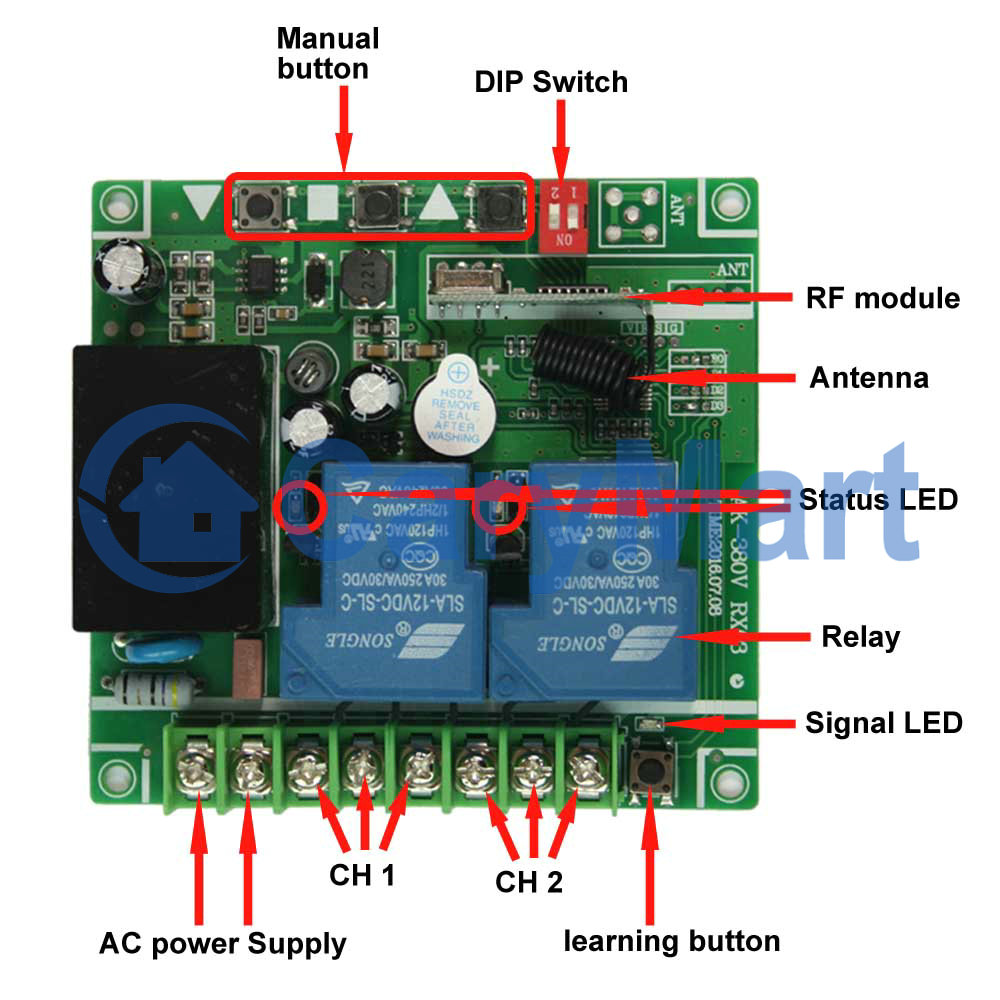
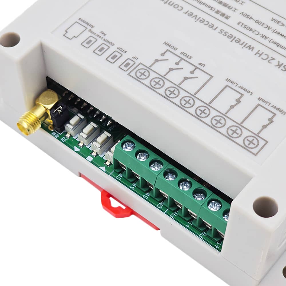
With three manual buttons: You can control the equipment by manual buttons.
With wired control terminals: You can connect manual switches to control the
equipment.
With limit control terminals: You can connect sensors, limit switches or
external devices to stop the equipment.
With 2 pins for switching the type of normally open or normally closed limit
switch.
With a DIP switch for switching working modes, offering four operating
modes.
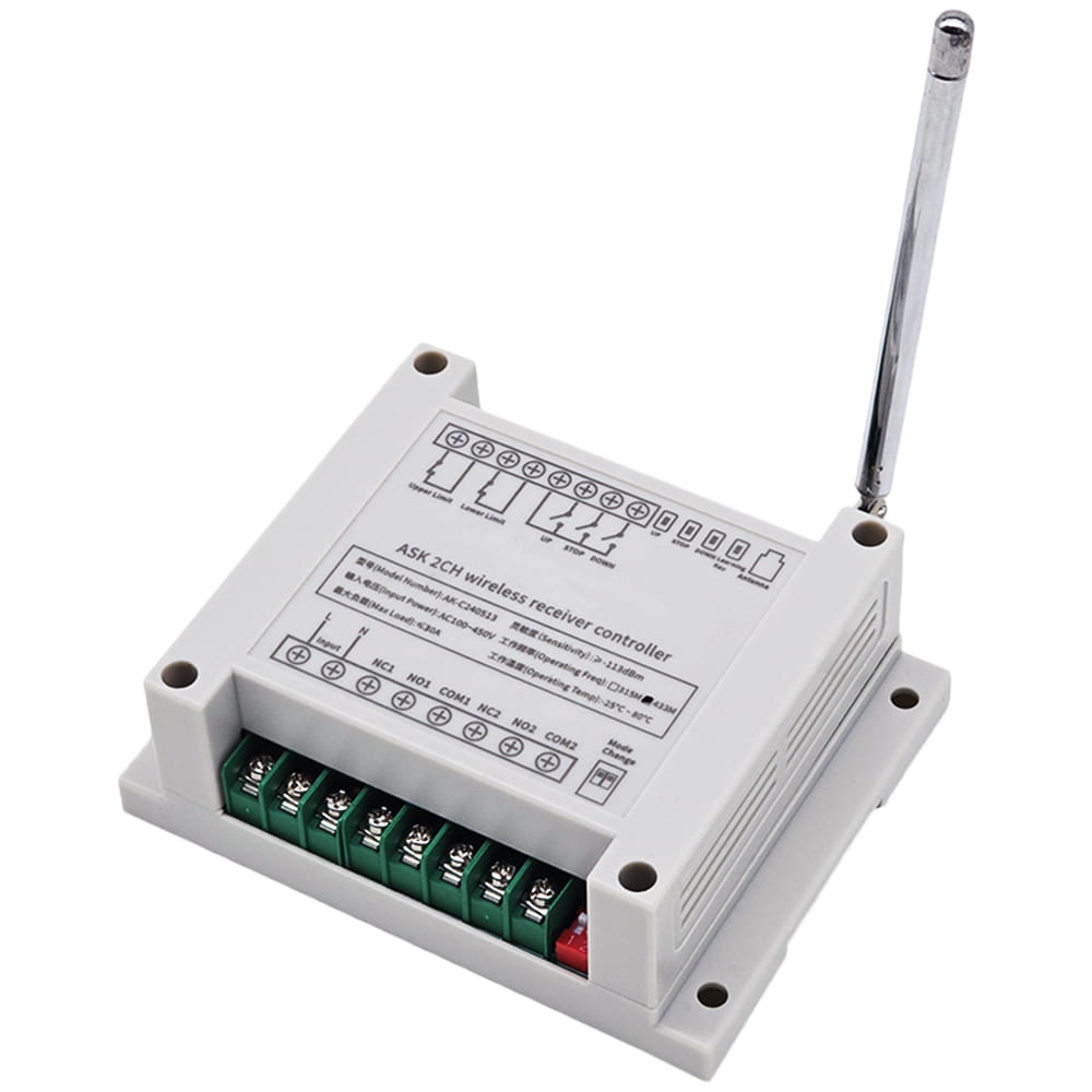
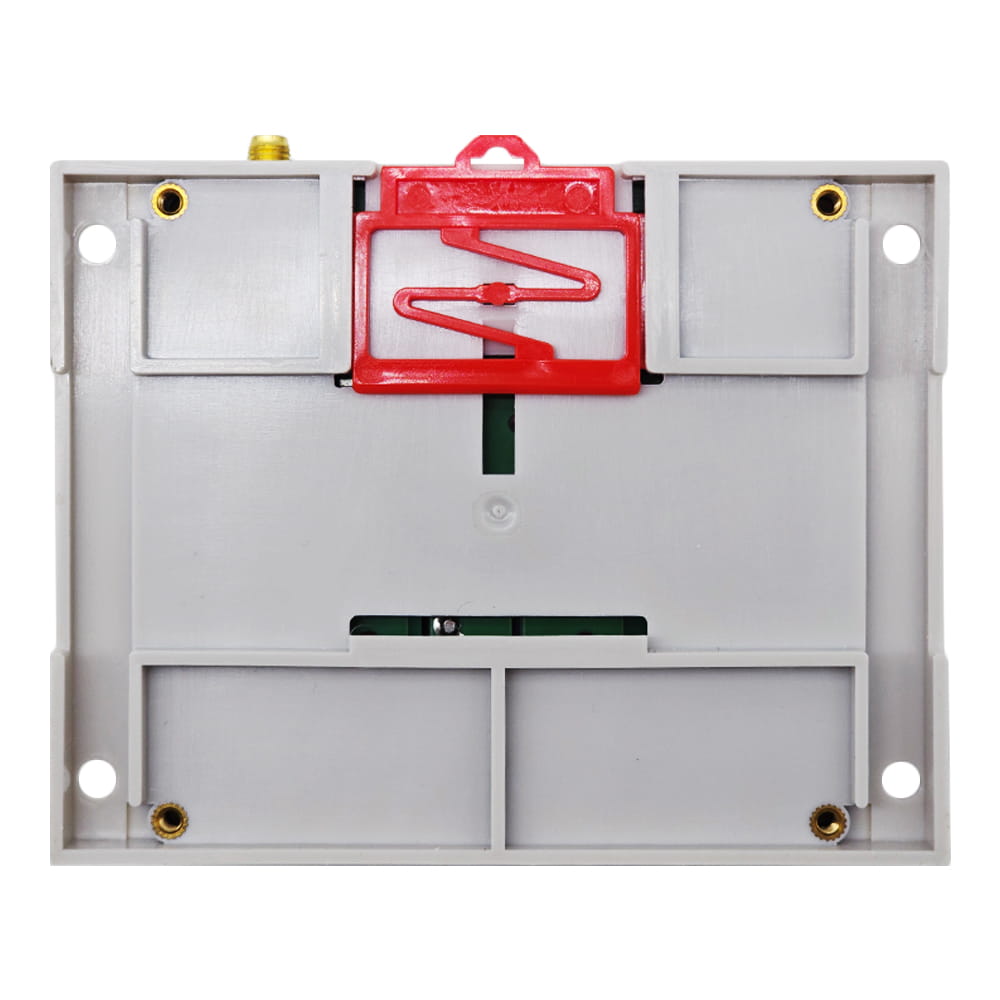
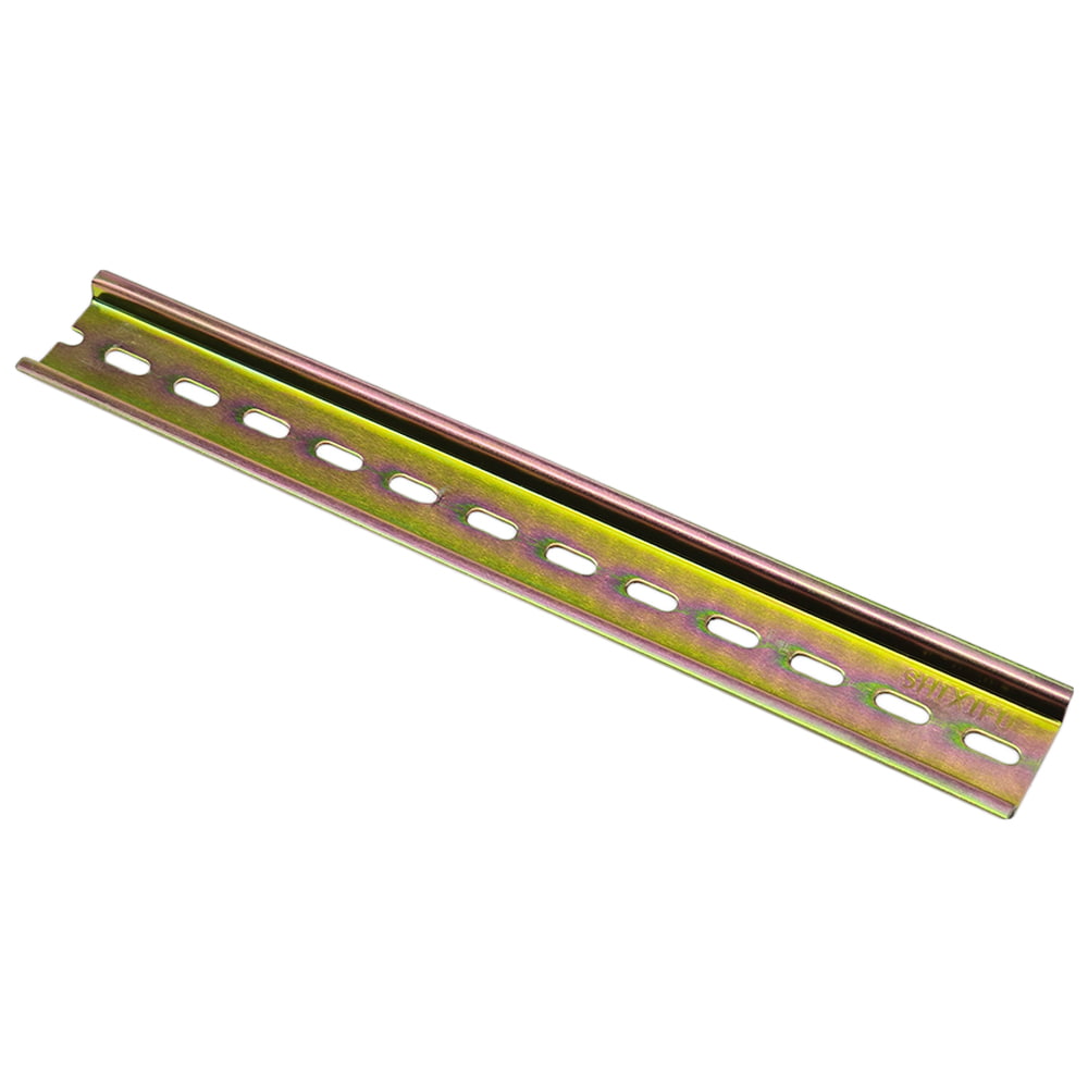
With guide rail buckle and screw holes: The back of the receiver is equipped
with a guide rail buckle and screw holes, which can be mounted on a 35mm
guide rail or directly fixed with screws.
With external antenna, the receiver have a farther working range.
The transmitter / remote can control the receiver from any place within a
reliable working distance.
Wireless RF signal from the transmitter can pass through walls, floors,
doors, or windows, but it will lose some operating range.
The receiver has reverse voltage protection and overcurrent protection.
The receiver can only be triggered by paired transmitters.
Two or more receivers may be used in the same area.
One or more transmitters / remotes can control one or several receivers
simultaneously.
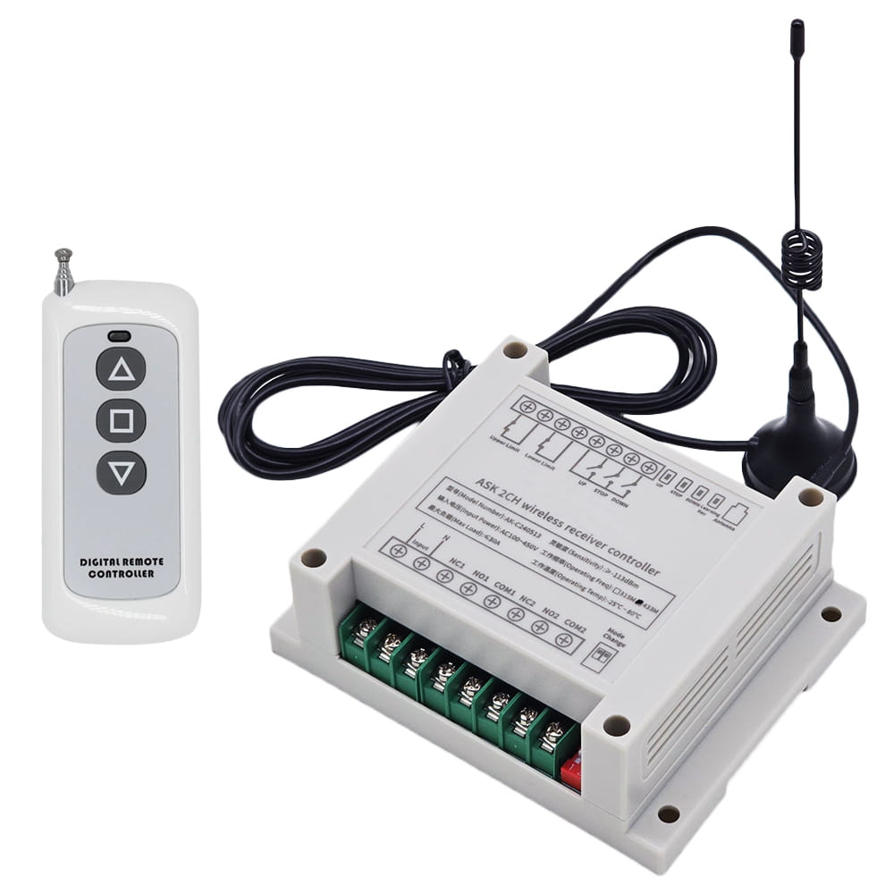
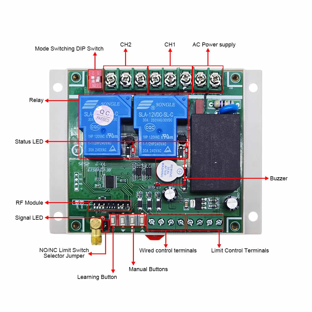
Receiver Parameters:
Model: S2PU-AC380-ANT3
Operating Voltage: AC 100V~450V (110V/120V/220V/240V/380V)
Working Frequency: 433MHz
Channel: 2 CH
Static Current: <30mA
Output Type: Relay output (Normally open and normally closed)
Maximum Load Current: 30 A / each channel
Suitable Wires for Connecting Terminals: 22-14 AWG
4 Selectable Working Modes: Self-locking, Momentary, Interlocking, Momentary
+ Self-locking
Receiver Sensitivity: ≥-113dBm
Operating Temperature: -25 ° C to +80 ° C
PCB size: 92 x 86 x 23 mm (3.6 x 3.4 x 0.9 inches)
Case size: 115 x 90 x 40 mm (4.5 x 3.5 x 1.6 inches)
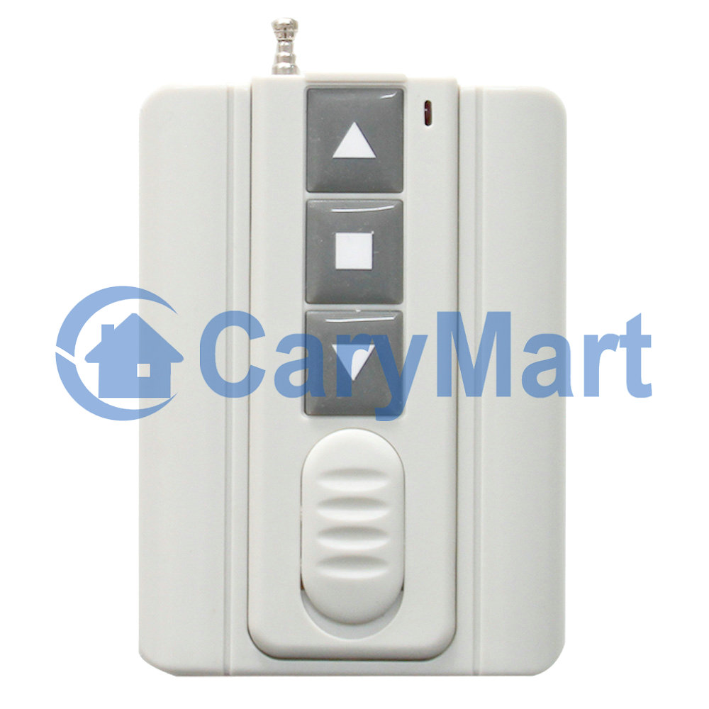
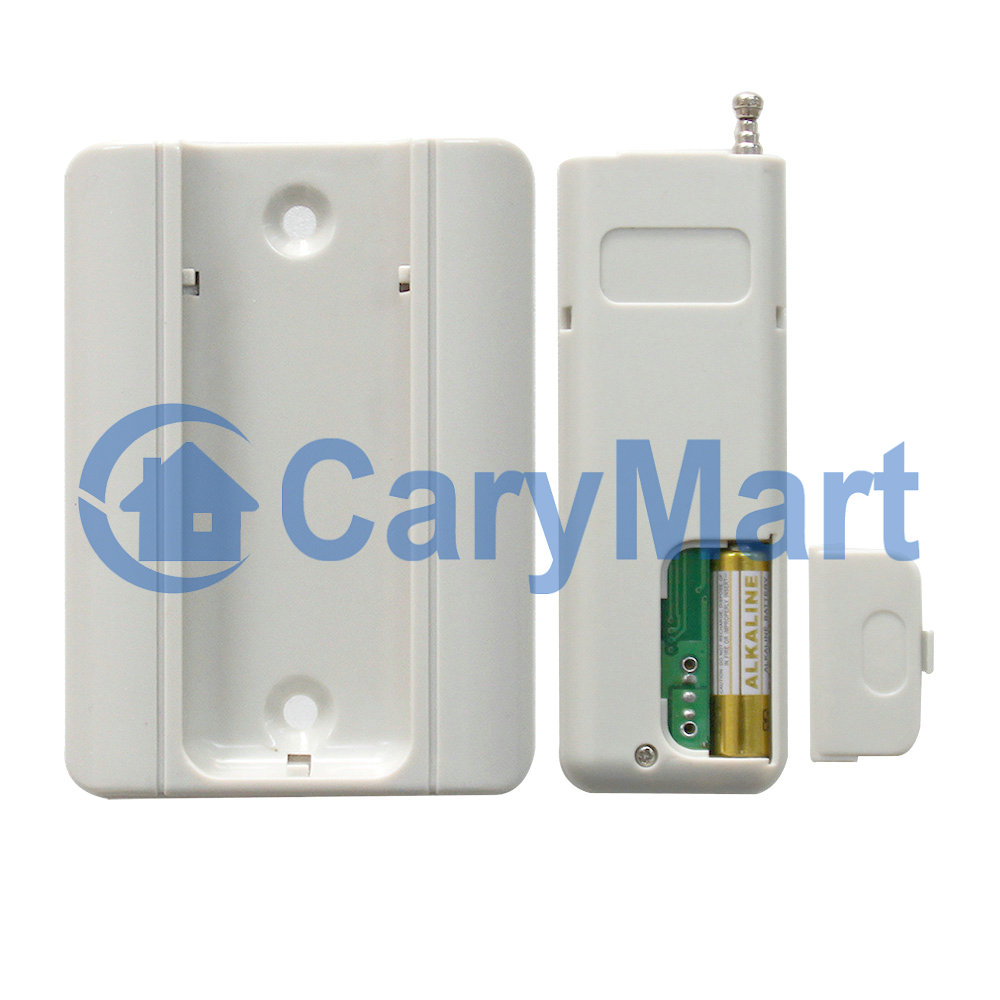
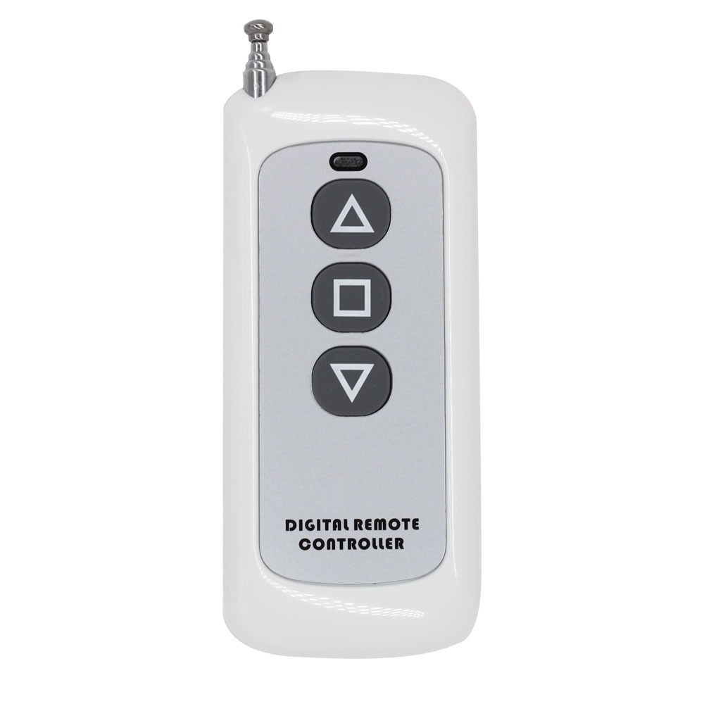
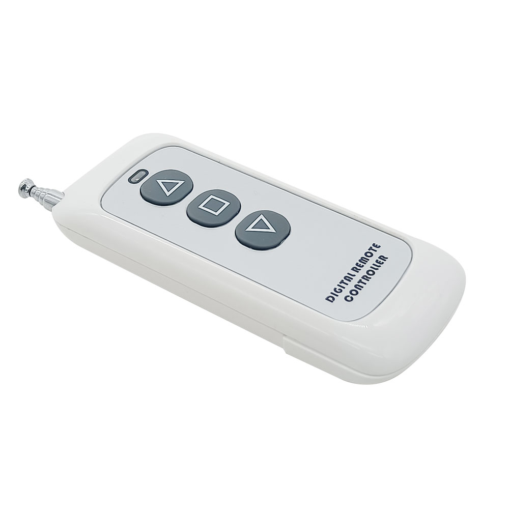
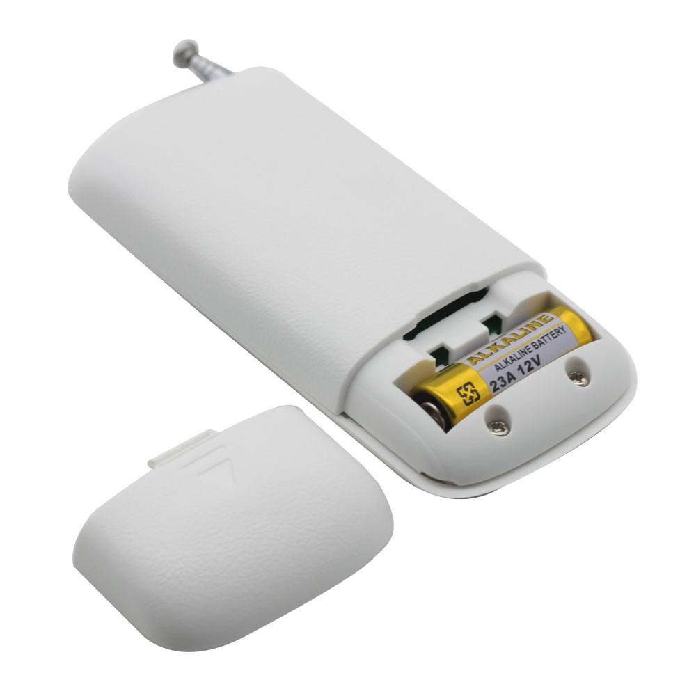
Transmitter Parameters:
Model: 0021126 (CP-3L)
Channel/Button: 3
Button Symbol:▲■▼
Operating Voltage: 12V (1 x 23A -12V battery, can be used for 12 months)
Standby current: 4uA
Operating Current: 14mA
Operating Frequency: 433Mhz
Encoding Chip: EV1527
Transmitting Distance: 500m / 1500ft (theoretically)
Modulation Mode: ASK
Operating Temperature: -20 ° C to +70 ° C
Unit Size: 92 x 40 x 15 mm
Matching Transmitters:
The receiver can work with different transmitters, such as model
C-2L /
C-3-2L (100M),
CP-2L /
CP-3L (500M) or
CB-2L
(1000M) etc.
Working Range:
This receiver and different transmitters form a complete set, which can
achieve different working distances. For example, when it and the
transmitter CP-3L form a complete set, the maximum working distance may
reach 1500 feet or 500 meters in an open area.
The maximum working distance is based on theoretical data without obstacles
and any RF interference. In practice, it will be hindered by trees, walls,
or other construction, and will be interfered with by other wireless
signals. Therefore, the actual working distance may not reach this maximum
distance.
If you need a longer working distance, you can replace the antenna on the
receiver, or use an RF signal repeater, or use a powerful transmitter, such
as CB series.
Usage:
The receiver can be used to control both 0~28VDC and AC 100~450V equipment.
Notice: The receiver is relay output, not DC/AC power output. Initial state
of relay output terminals: Terminals NO and COM are Normally Open;
Terminals NC and COM are Normally Closed.
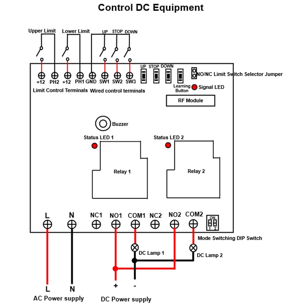
Wiring: 1) Wiring for DC lamp:
If you want to control DC lamp, do as follows. Please refer to the
connection diagram.
1.1 Connect the live wire of AC power supply to terminal L, and connect
the neutral wire of AC power supply to terminal N.
1.2 Connect terminal NO to the positive pole of DC power supply, connect
terminal COM to the positive pole of DC lamp, and connect the negative
pole of DC lamp to the negative pole of DC power supply.
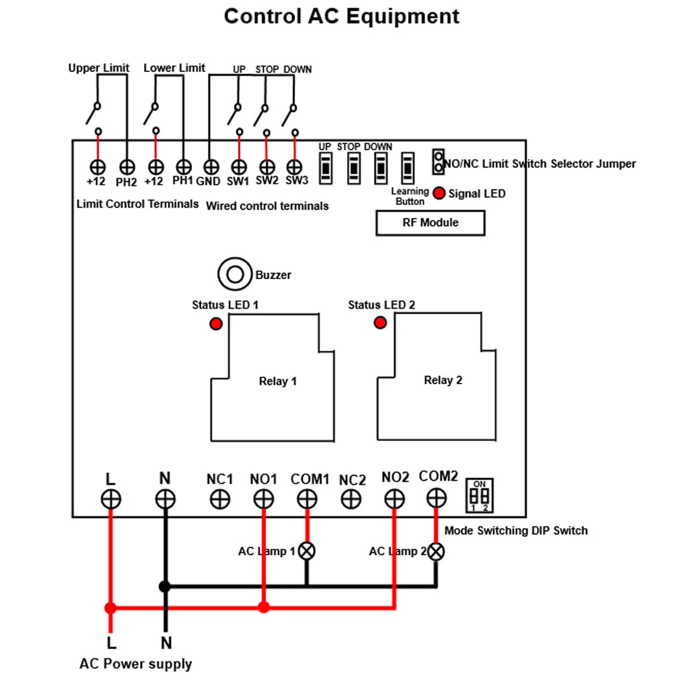
2) Wiring for AC lamp:
If you want to control the AC lamp, do as follows. Please refer to the
connection diagram.
2.1 Connect the live wire of AC power supply to terminal L, and connect
the neutral wire of AC power supply to terminal N.
2.2 Connect terminal NO to the live wire of AC power supply, connect
terminal COM to one side of AC lamp, and connect another side of AC lamp
to the neutral wire of AC power supply.
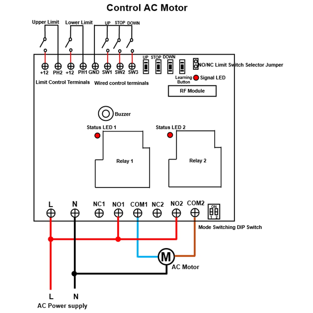
3) Wiring for AC motor:
If you want to control small bi-directional AC motor (three control lines),
do as follows. Please refer to the connection diagram.
3.1 Connect the live wire of AC power supply to terminal L, and connect
the neutral wire of AC power supply to terminal N.
3.2 Connect the live wire of the AC power supply to the terminal NO of the
two relays, connect the neutral wire of the AC power supply to the common
wire of the AC motor.
3.3 Connect the forward and reverse wires of the AC motor to the terminal
COM of the two relays, and you can exchange these two wires to change the
rotating direction of motor.
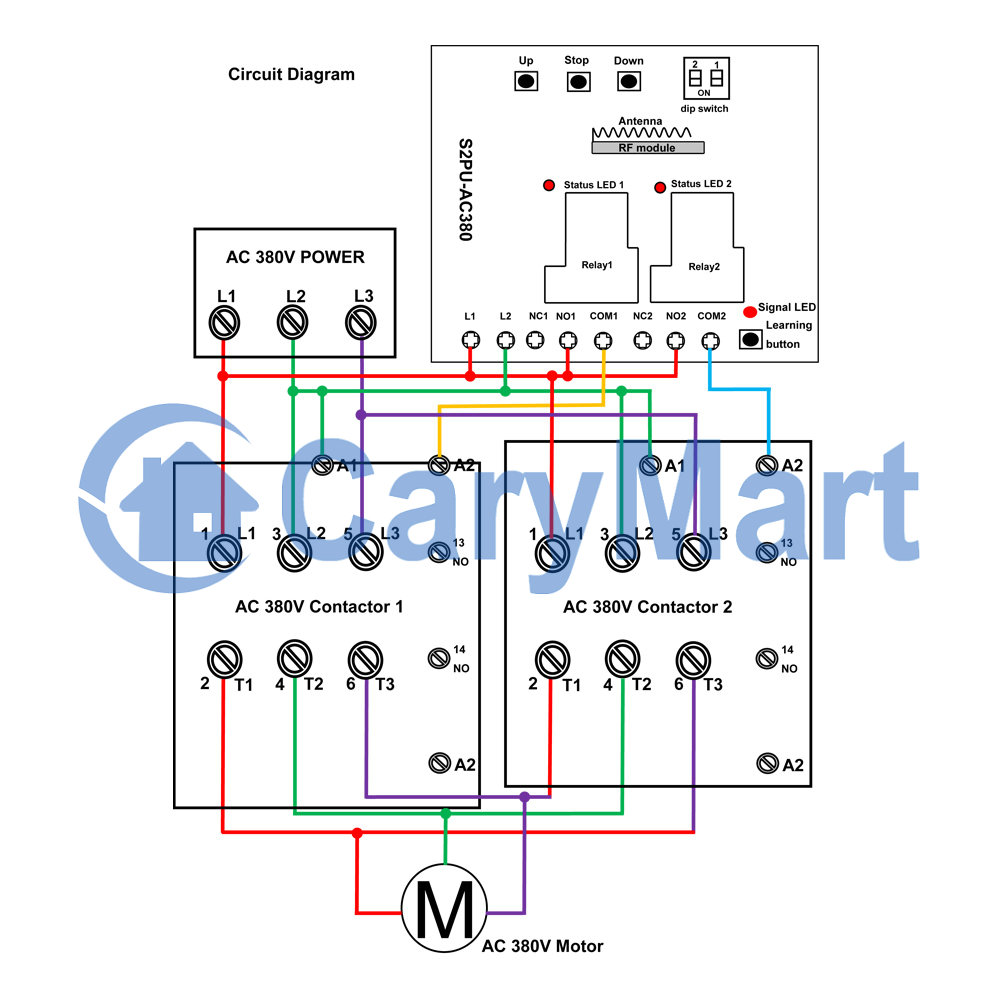
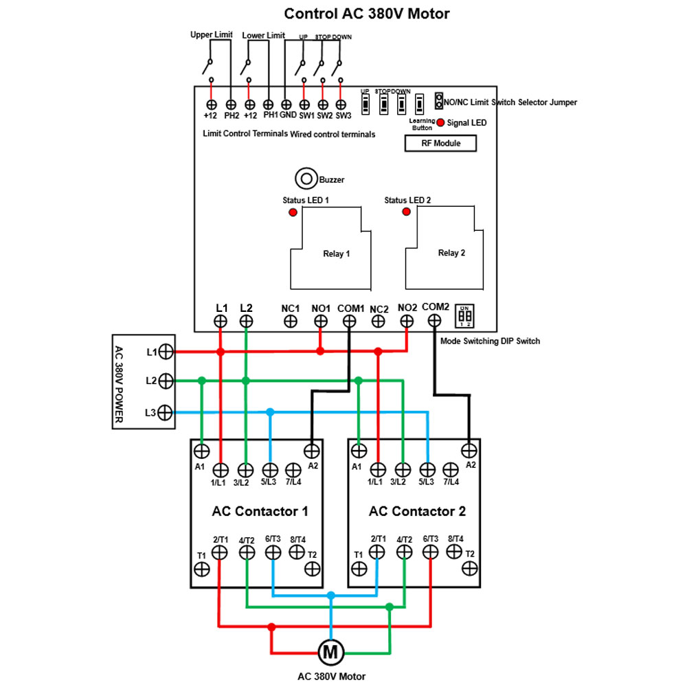
4) Wiring for AC 380V motor:
If you want to control AC 380V motor, please refer to the connection
diagram.
Setting different control modes:
The receiver will be set in Self-locking mode before leaving the factory, if
you want to use another mode, please follow the following steps:
1) Setting Momentary mode: Turn off the first bit and the second bit of the
dip switch, the signal LED flashes 1 time and the buzzer sounds 1 time.
The operation of Momentary mode with the transmitter CP-2L:
Press and hold the button ▲ on the transmitter: The relay 1 is activated,
two terminals NO1 and COM1 of Relay 1 are connected, two terminals
NC1 and COM1 are disconnected.
Release the button ▲ : The relay 1 is deactivated, two terminals NO1 and
COM1 of Relay 1 are disconnected, two terminals NC1 and COM1 are
connected.
Press and hold the button ▼ on the transmitter: The relay 2 is activated,
two terminals NO2 and COM2 of Relay 2 are connected, two terminals NC2 and COM2 are disconnected.
Release the button ▼ : The relay 2 is deactivated, two terminals NO2 and COM2 of Relay 2 are disconnected, two terminals NC2 and COM2 are
connected.
The operation of Momentary mode with the manual buttons on the receiver:
Press and hold the button UP on the receiver: The relay 1 is activated.
Release the button UP: The relay 1 is deactivated.
Press and hold the button DOWN on the receiver: The relay 2 is activated.
Release the button DOWN: The relay 2 is deactivated.
2) Setting Self-locking mode: Turn on the first bit and turn off the second
bit of the dip switch, the signal LED flashes 2 times and the buzzer sounds
2 times.
The operation of Self-locking mode with the transmitter CP-2L:
Press the button ▲ on the transmitter: The relay 1 is activated, two
terminals NO1 and COM1 of Relay 1 are connected, two terminals NC1
and COM1 are disconnected.
Press the button ▲ again: The relay 1 is deactivated, two terminals NO1
and COM1 of Relay 1 are disconnected, two terminals NC1 and COM1 are
connected.
Press the button ▼ on the transmitter: The relay 2 is activated, two
terminals NO2 and COM2 of Relay 2 are connected, two terminals NC2
and COM2 are disconnected.
Press the button ▼ again: The relay 2 is deactivated, two terminals NO2
and COM2 of Relay 2 are disconnected, two terminals NC2 and COM2 are
connected.
The operation of Self-locking mode with the manual buttons on the receiver:
Press the button UP on the receiver: The relay 1 is activated.
Press the button UP again: The relay 1 is deactivated.
Press the button DOWN on the receiver: The relay 2 is activated.
Press the button DOWN again: The relay 2 is deactivated.
3) Setting Interlocking mode: Turn off the first bit and turn on the second
bit of the dip switch, the signal LED flashes 3 times and the buzzer sounds
3 times.
The operation of Interlocking mode with the transmitter CP-3L:
Press the button ▲ on the transmitter: The relay 1 is activated, two
terminals NO1 and COM1 of Relay 1 are connected, two terminals NC1
and COM1 are disconnected.
Press the button ■ on the transmitter: The relay 1 is deactivated, two
terminals NO1 and COM1 of Relay 1 are disconnected, two terminals
NC1 and COM1 are connected.
Press the button ▼ on the transmitter: The relay 2 is activated, two
terminals NO2 and COM2 of Relay 2 are connected, two terminals NC2
and COM2 are disconnected.
Press the button ■ on the transmitter: The relay 2 is deactivated, two
terminals NO2 and COM2 of Relay 2 are disconnected, two terminals NC2 and COM2 are connected.
The operation of Interlocking mode with the manual buttons on the receiver:
Press the button UP on the receiver: The relay 1 is activated.
Press the button STOP on the receiver: The relay 1 is deactivated.
Press the button DOWN on the receiver: The relay 2 is activated.
Press the button STOP on the receiver: The relay 2 is deactivated.
4) Setting Momentary (Channel 1) + Self-locking (Channel 2) mode: Turn on
the first bit and the second bit of the dip switch, the signal LED flashes 4
times and the buzzer sounds 4 times.
Wired control terminals:
The receiver has wired control terminals, and you can connect external
devices (with normally open contact), such as manual switches to wired
control terminals, then use them to control the equipment.
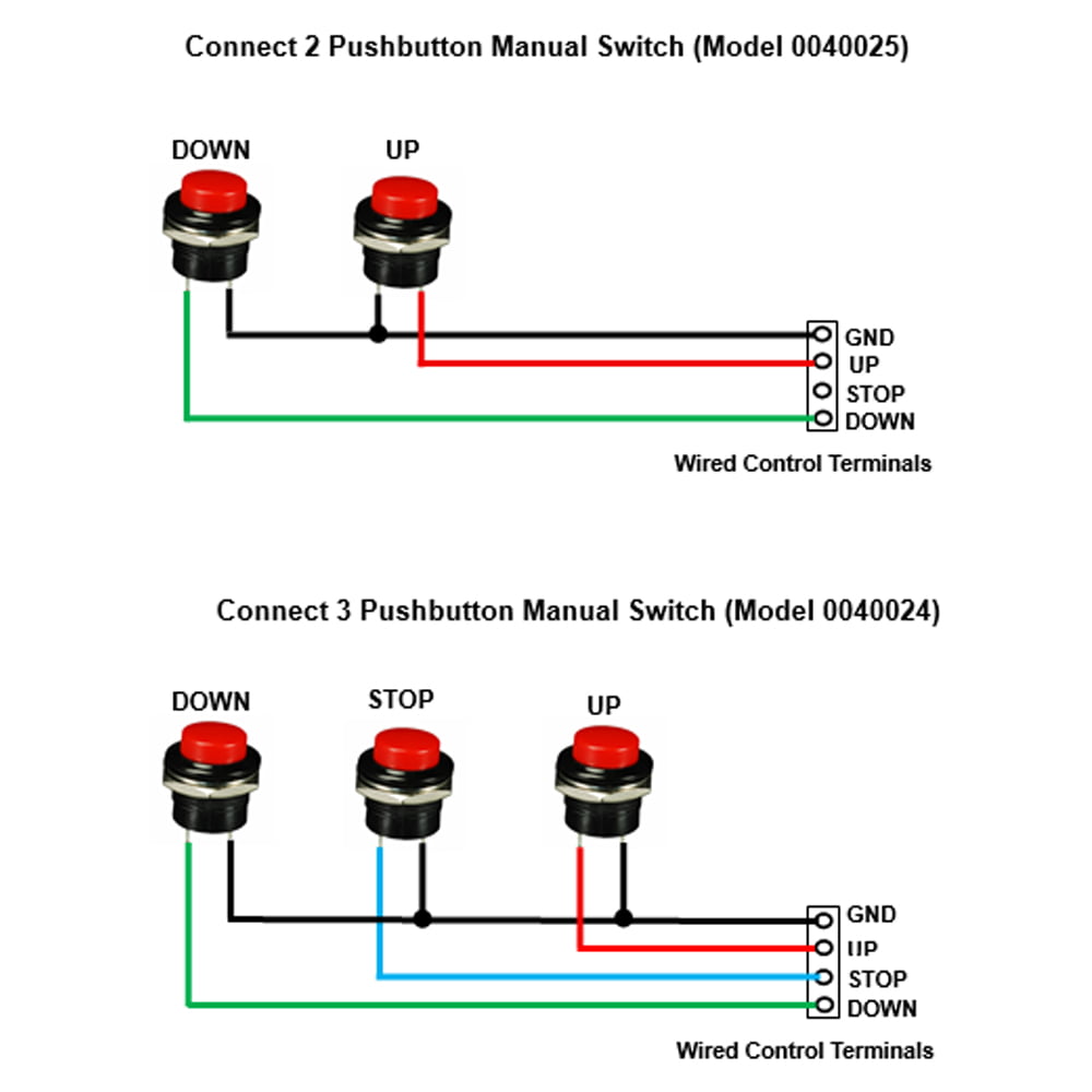
For example, you can connect two or three manual switches to wired control
terminals UP, DOWN, STOP and GND according to following wiring
diagram.
1) In Momentary mode: For example, connect 2 pushbutton manual switch (Model
0040025).
When pressing and holding the UP button, two terminals UP and GND are
connected, then the relay 1 is activated. And when releasing the UP button,
two terminals UP and GND are disconnected, then the relay 1 is
deactivated.
When pressing and holding the DOWN button, two terminals DOWN and GND
are connected, then the relay 2 is activated. And when releasing the DOWN
button, two terminals DOWN and GND are disconnected, then the relay 2 is
deactivated.
2) In Self-locking mode: For example, connect 2 pushbutton manual switch
(Model 0040025).
When pressing the UP button, two terminals UP and GND are connected, then
the relay 1 is activated. And when pressing the UP button again, two
terminals UP and GND are disconnected, then the relay 1 is deactivated.
When pressing the DOWN button, two terminals DOWN and GND are connected,
then the relay 2 is activated. And when pressing the DOWN button again, two
terminals DOWN and GND are disconnected, then the relay 2 is
deactivated.
3) In Interlocking mode: For example, connect 3 pushbutton manual switch
(Model 0040024).
When pressing the UP button, two terminals UP and GND are connected,
then the relay 1 is activated. And when pressing the STOP button, two
terminals STOP and GND are connected, then the relay 1 is deactivated.
When pressing the DOWN button, two terminals DOWN and GND are connected,
then the relay 2 is activated. And when pressing the STOP button, two
terminals STOP and GND are connected, then the relay 2 is deactivated.
Limit control terminals:
The receiver has limit control terminals, and you can connect external
devices (with normally closed or normally open contact), such as sensors,
limit switches to limit terminals, then use them to stop the equipment.
And the receiver has two pins for switching the type of normally open or
normally closed limit switch. Note: The receiver needs to be restarted after switching the limit switch
type.
For example, when you short two pins with a jumper cap, you can connect a
normally closed limit switch to the two terminals of Upper Limit, and
connect another normally closed limit switch to the two terminals of Lower
Limit.
When motor rotates in positive direction, if disconnect two terminals of
Upper Limit, the motor will stop automatically.
When motor rotates in reversal direction, if disconnect two terminals of
Lower Limit, the motor will stop automatically.
For example, when you do not short two pins, you can connect a normally open
limit switch to the two terminals of Upper Limit, and connect another
normally open limit switch to the two terminals of Lower Limit.
When motor rotates in positive direction, if connect two terminals of Upper
Limit, the motor will stop automatically.
When motor rotates in reversal direction, if connect two terminals of Lower
Limit, the motor will stop automatically.
Note:
When the limit switch terminals of the receiver are set to normally closed
type, if you are not using the limit switch, you need to short-circuit the
upper and lower limit switch terminals respectively.
When the limit switch terminals of the receiver are set to normally open
type, if you are not using the limit switch, you do not need to
short-circuit the upper and lower limit switch terminals.
How to pair the transmitter to the receiver:
Notice: We have paired the transmitter to the receiver before leaving the
factory. If you want to pair more transmitters, please follow the following
steps.
1) Pairing the button ▲ on the transmitter to the receiver:
1.1 Press the learning button in the receiver once, the signal LED on the
receiver flashes once and then stays on, it means the receiver enters the
learning state.
1.2 Press the button ▲ on the transmitter; if the buzzer sounds 4 times, it
means the pairing of button ▲ is successful.
2) Pairing the button ▼ on the transmitter to the receiver:
2.1 Press the learning button in the receiver twice, the signal LED on the
receiver flashes twice and then stays on, it means the receiver enters the
learning state.
2.2 Press the button ▼ on the transmitter; if the buzzer sounds 4 times, it
means the pairing of button ▼ is successful.
3) The receiver can learn 20 two-button transmitters with different codes.
Note: The receiver is only compatible with transmitters that use learning
codes. If the receiver does not receive a pairing signal within 5 seconds
after entering the learning state, the receiver will exit the learning
state.
How to delete all transmitters codes stored in the receiver:
Notice: We have learned the transmitter to the receiver. If you don’t want
the receiver to work with the transmitter, you can delete all codes of the
transmitters which are stored in the receiver.
Operation: Press and hold the learning button on the receiver for 8-9
seconds, then the buzzer sounds 8 times. This indicates that all stored
codes have been deleted successfully.
Package Include:
1 x Receiver: S2PU-AC380-ANT3
1 x Transmitter: CP-3L
1 x User manual