Hi, I'm Tom. Welcome to our shop,
Carymart offers you the premium rf remote control equipment.
We suggest you reading our FAQs before making your decision.
If you have any other question, please contact us.
We will reply you as soon as possible.
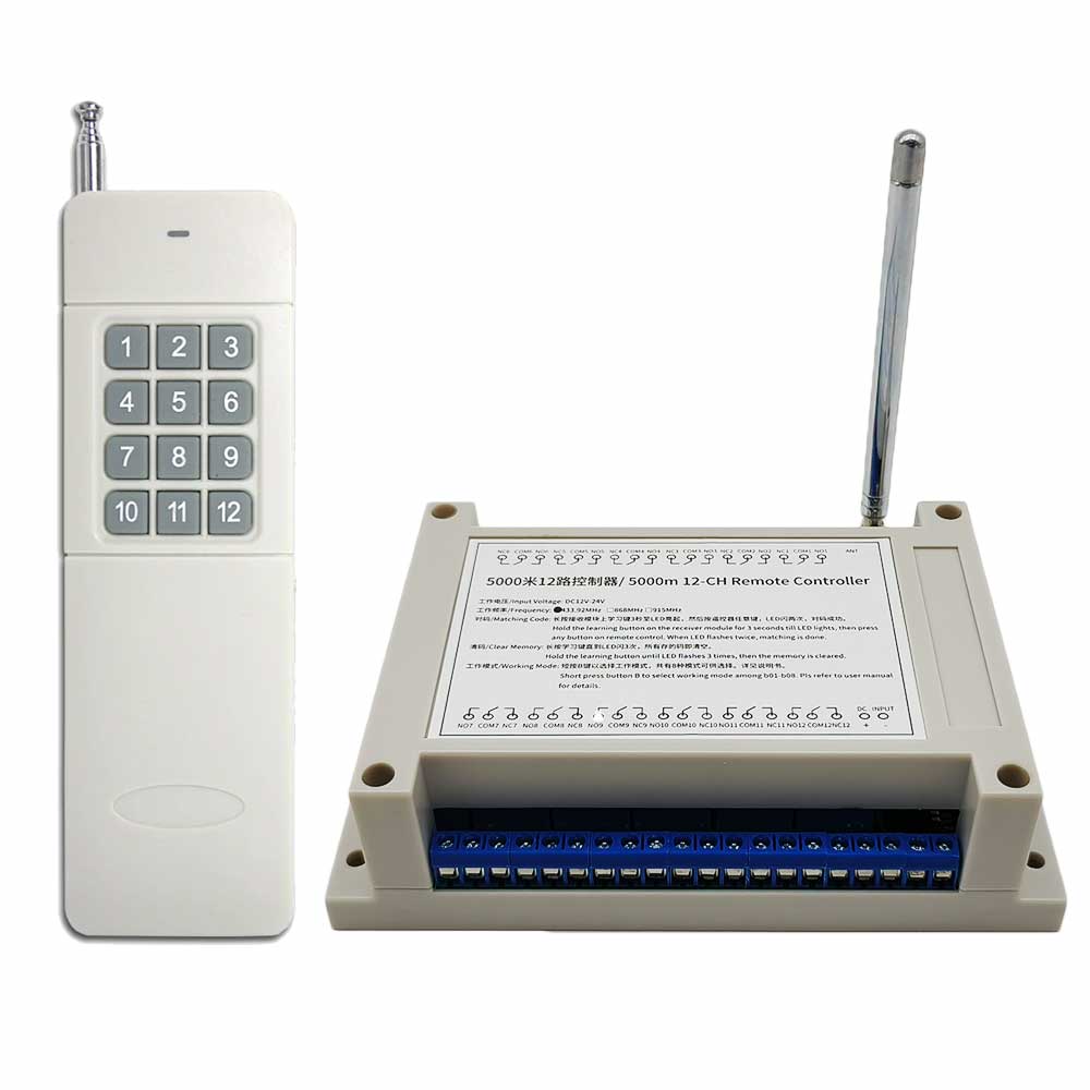
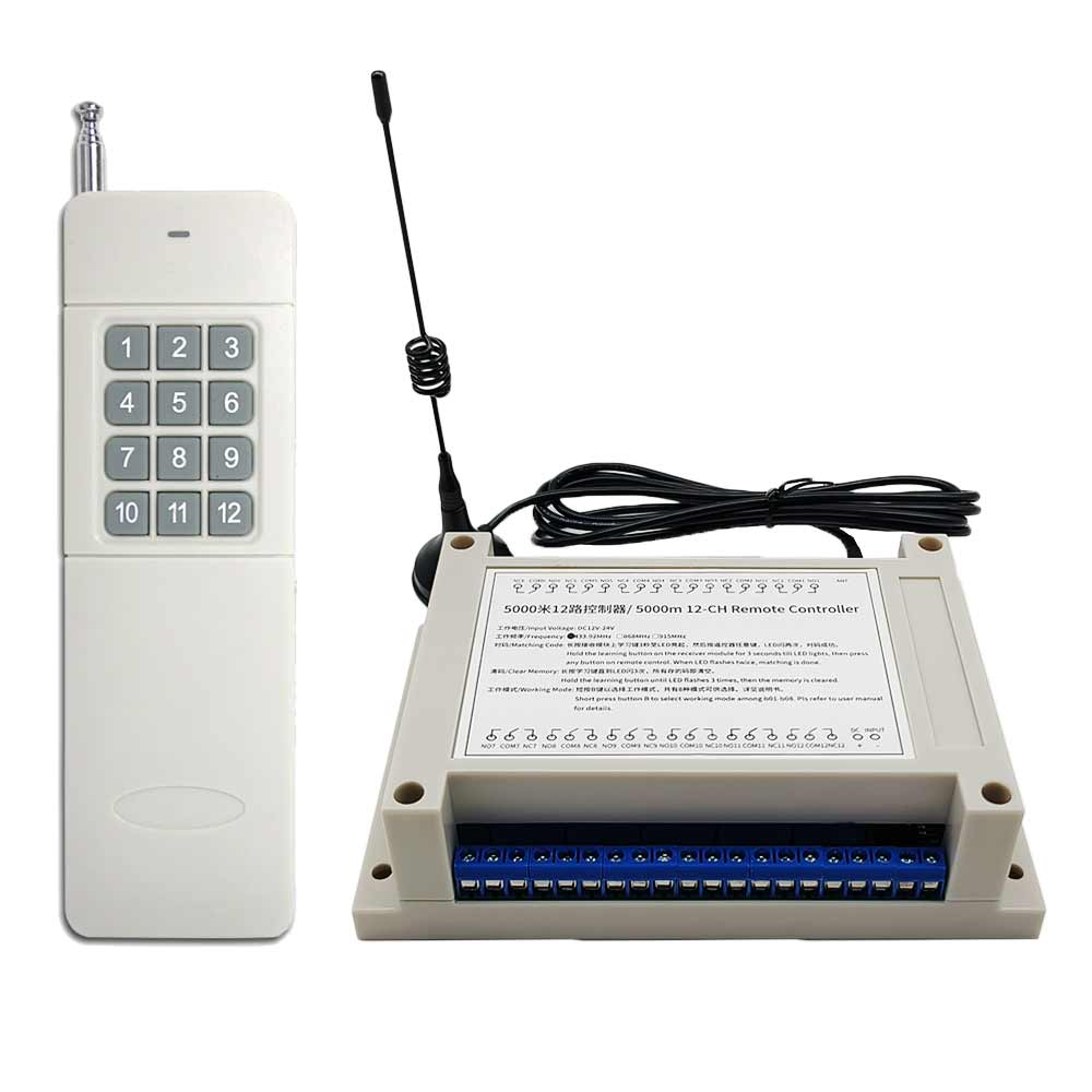
Package Include:
1 x Receiver: S12UW-DC-ANT3
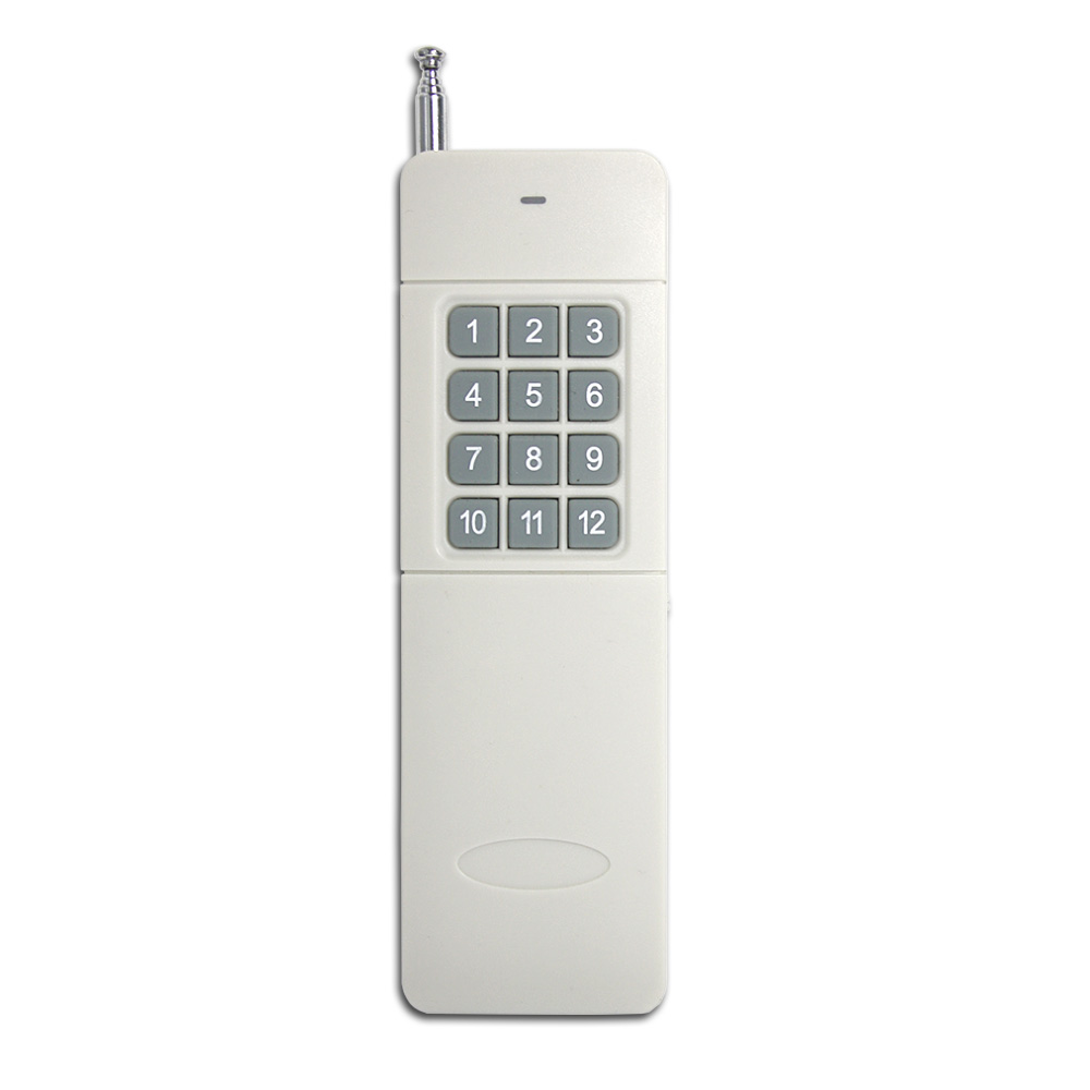
1 x Transmitter: CC-12
1 x User manual
Introduction:
This receiver is a super long range remote switch. It is developed by LORA
(Long Range) wireless communication technology, so it has ultra-long working
distance, ultra-high receiving sensitivity, superior anti-interference
ability, and smaller power consumption. It uses a transceiver chip to
implement bidirectional communication. It’s ideal working distance is up to
5 kilometers, which is an excellent device for remote control and
long-distance communication.
Application:
This receiver is an electric device with 12 dry relay outputs, it and the
transmitter form a wireless remote-control system. This system may be used
in all types of industry automation, agriculture, business, home, factory,
house, farm, garage, vehicle, ship, aerial vehicle, etc. It can remote
control different AC or DC equipment on land, water, and air, such as
lights, doors, windows, lamps, sockets, locks, sirens, outlets, heaters,
motors, fans, winches, curtains, blinds, linear actuators, electric solenoid
valves, and security alarm systems. The applications are endless.
Feature:
Wireless control, easy to install.
Super long working range: With the transmitter forming a complete set, the
maximum working distance may reach 5000 meters in an open area.
Two operating voltage versions: DC 12V, 24V optional.
Relay Output: This receiver is dry relay output; it can be used to operate
both DC and AC equipment. The output terminals are NO / NC (normally open /
normally closed), serving as a switch.
With working mode button: 8 different working modes can be switched.
With working mode display screen: Different numbers on the LED screen
correspond to different working modes.
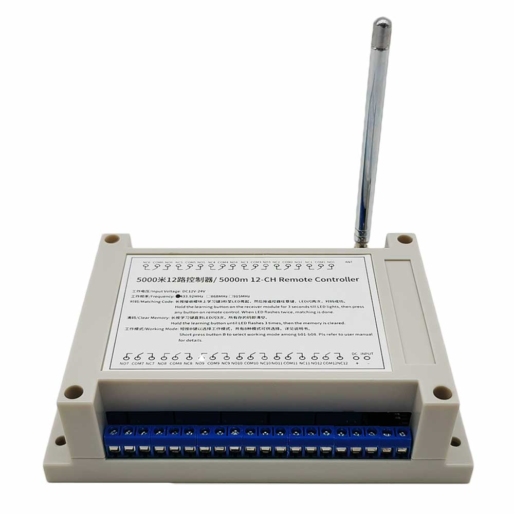
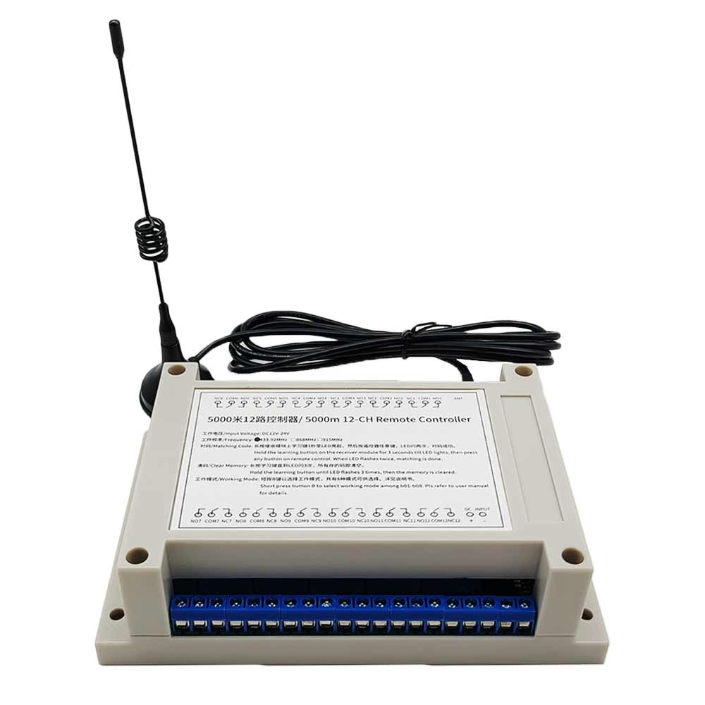
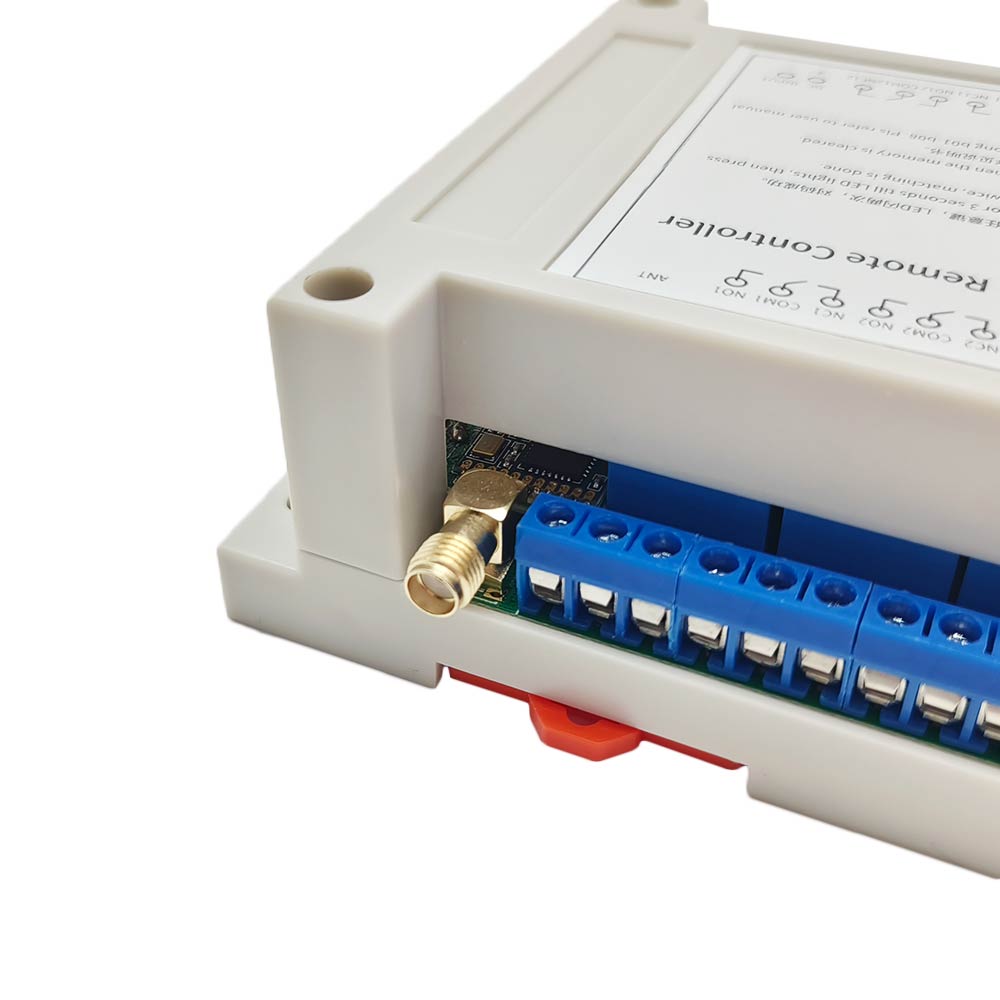
With external antenna, the receiver has a farther working range.
The transmitter / remote can control the receiver from any place within a
reliable working distance.
Wireless RF signal from the transmitter can pass through walls, floors,
doors, or windows, but it will lose some operating range.
The receiver has reverse voltage protection and overcurrent protection.
The receiver can only be triggered by paired transmitters.
One or more transmitters / remotes can control one or several receivers
simultaneously.
Two or more receivers may be used in the same area.
Feedback Function:
The receiver and the transmitter have a Two-way working mode, so the user
can know the working status of the receiver by the transmitter.
Two-way working mode: When the receiver is successfully triggered by the
signal from the transmitter, it will immediately transmit a feedback signal
to the transmitter. When the transmitter receives this signal, it will send
out a buzzing sound to inform you that the receiver has been successfully
triggered.
Receiver Parameters:
Model: S12UW-DC-ANT3
Operating Voltage: 9~28VDC
Working Frequency: 433.92 MHz
Quiescent Current: ≤10mA
Channel: 12 CH
Output Type: Dry Relays Output (With Normally Open and Normally Closed
Terminals)
Maximum Load Voltage of Relay: 240VAC or 28VDC
Maximum Load Current of Relay: 10A / channel
Suitable Wires for Connecting Terminals: 22-12 AWG
8 Different Control Modes: Self-locking, Momentary, Interlocking, and 5
Mixed modes
Operating Temperature: -20 °C ~ +70 °C
PCB size: 122 x 87 x 18 mm (4.8x 3.4 x 0.7 inches)
Case size: 145 x 90 x 40 mm (5.7 x 3.5 x 1.6 inches)
Transmitter Parameters:
Model: 0021078 (CC-12)
Channel / Button: 12
Button Symbol: 1, 2, 3, 4, 5, 6, 7, 8, 9, 10, 11, 12
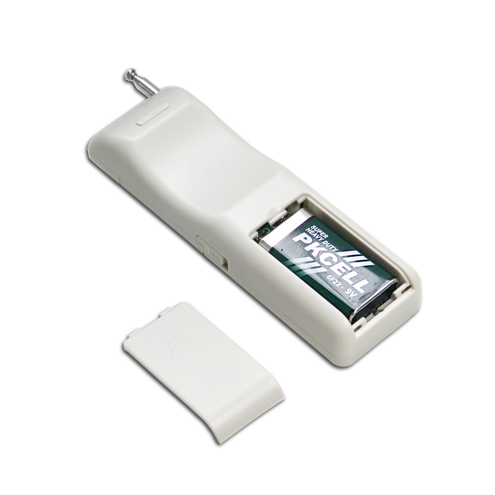
Operating Voltage: 9V (1 x 6F22-9V battery, can be used for 12 months)
Quiescent Current: 5μA
Working Current: 65mA (when the transmitter is transmitting the signal),
16mA( when the transmitter is receiving the signal).
Operating Frequency: 433.92 MHz
Modulation Mode: FSK + LORA
Feedback indication: buzzing sound
Transmitting Distance: 5000 meters / 15000 feet (theoretically)
With power switch on the side.
Operating Temperature: -20°C ~ +70°C
Unit Size: 135 x 42 x 25 mm (5.3 x 1.7 x 1.0 inches)
Matching Transmitters:
This receiver only works with 5000m transmitters, such as model
CC-12
(5000 Meter / 15000 feet range).
Super Long Working Range:
The receiver and the transmitter form a complete kit, the maximum working
distance may reach 15000 feet or 5000 meters in an open area.
The maximum working distance is a theoretical data, it shall be operated in
an open ground, no barriers, no interference. But in the practice, it will
be hindered by trees, walls, or other construction, and will be interfered
by other wireless signals. Therefore, the actual working distance may not
reach this maximum distance.
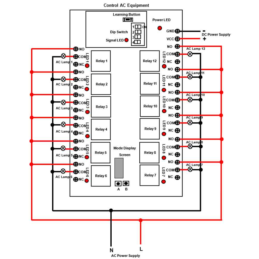
Usage:
The receiver can be used to control both 0~28VDC and 110~240VAC devices.
Notice: The receiver is dry relay output, not DC/AC power output. Initial
state of relay output terminals: Terminals <NO> and <COM> are Normally Open;
Terminals <NC> and <COM> are Normally Closed.
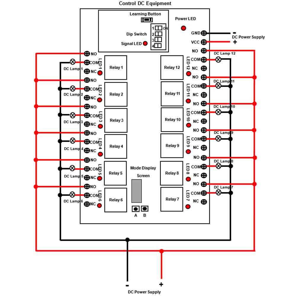
Wiring:
1) If you want to control a DC 12V lamp, do as following:
1.1 Connect the positive pole of DC power supply to terminal <VCC> and
connect the negative pole of DC power supply to terminal <GND>.
1.2 Connect terminal <NO> to the positive pole of DC power supply, connect
terminal <COM> to the positive pole of DC lamp, and connect the negative
pole of DC lamp to the negative pole of DC power supply.
2) If you want to control an AC 220V lamp, do as following:
2.1 Connect the positive pole of DC power supply to terminal <VCC> and
connect the negative pole of DC power supply to terminal <GND>.
2.2 Connect terminal <NO> to the live wire of AC power supply, connect
terminal <COM> to one side of AC lamp, and connect another side of AC lamp
to the neutral wire of AC power supply.
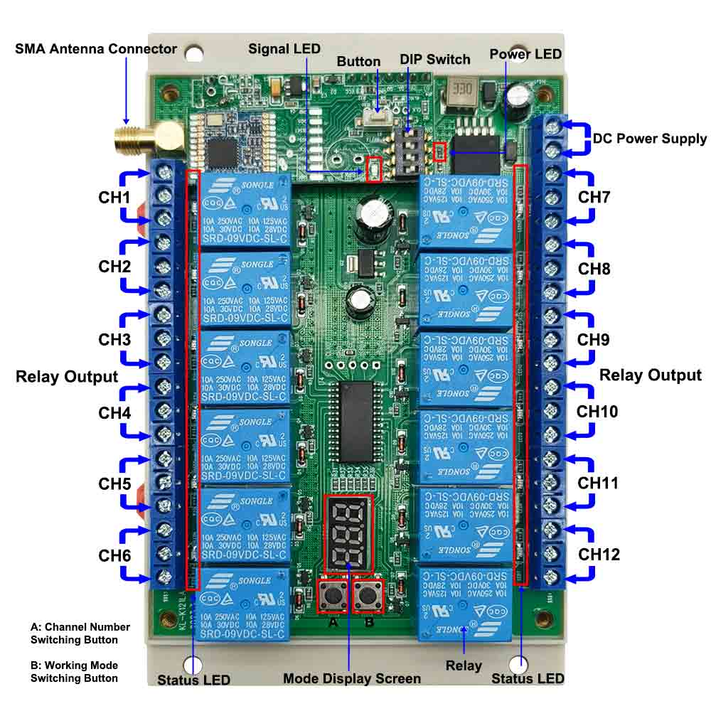
Switch the working mode or switch the number of operating channels:
The receiver has two buttons, button A is the channel number switching
button, and button B is the working mode switching button.
1) When the receiver is powered on, the LED screen will display "A12".
2) If you press and hold the button A for 2-3 seconds, the LED screen will
flash, and the receiver enters the channel number switching status. At this
time, you may press the button A to switch the display text of the LED
screen. The text will switch from A12 to A06 then to A08. A12 indicates that
all 12 channels of the receiver are operational. A06 indicates that only 6
channels of the receiver are operational. A08 indicates that only 8 channels
of the receiver are operational. If you again press and hold the button A
for 2-3 seconds, the LED screen stops flashing, and the receiver exits the
channel number switching status.
3) If you press and hold the button B for 2-3 seconds, the LED screen will
flash, and the receiver enters the working mode switching status. At this
time, you may press the button B to switch the display text of the LED
screen. The text will switch from b01 to b08. Different numbers correspond
to different working modes. If you again press and hold the button B for 2-3
seconds, the LED screen stops flashing, and the receiver exits the working
mode switching status.
Setting different working modes:
The receiver will be set in Self-locking mode before leaving the factory, if
you want to use another mode, please follow the following steps.
1) Setting Momentary mode: When the receiver is in the working mode
switching state, press button B until the LED screen displays "b01".
The operation of Momentary mode with the transmitter CC-12:
Press and hold the button 1 on the transmitter: The relay 1 in the receiver
is activated; Release the button 1: The relay 1 is deactivated.
Press and hold the button 2 on the transmitter: The relay 2 in the receiver
is activated; Release the button 2: The relay 2 is deactivated.
............
Press and hold the button 12 on the transmitter: The relay 12 in the
receiver is activated; Release the button 12: The relay 12 is deactivated.
2) Setting Self-locking mode: When the receiver is in the working mode
switching state, press button B until the LED screen displays "b02".
The operation of Self-locking mode with the transmitter CC-12:
Press the button 1 on the transmitter: The relay 1 in the receiver is
activated; Press the button 1 again: The relay 1 is deactivated.
Press the button 2 on the transmitter: The relay 2 in the receiver is
activated; Press the button 2 again: The relay 2 is deactivated.
............
Press the button 12 on the transmitter: The relay 12 in the receiver is
activated; Press the button 12 again: The relay 12 is deactivated.
3) Setting Interlocking mode: When the receiver is in the working mode
switching state, press button B until the LED screen displays "b03".
The operation of Interlocking mode with the transmitter CC-12:
Press the button 1 on the transmitter: The relay 1 in the receiver is
activated, and other 11 relays are deactivated.
Press the button 2 on the transmitter: The relay 2 in the receiver is
activated, and other 11 relays are deactivated.
............
Press the button 12 on the transmitter: The relay 12 in the receiver is
activated, and other 11 relays are deactivated.
4) Setting Momentary (Channels 1~6) + Self-locking (Channels 7~12) mode:
When the receiver is in the working mode switching state, press button B
until the LED screen displays "b04".
5) Setting Momentary (Channels 1~6) + Interlocking (Channels 7~12) mode:
When the receiver is in the working mode switching state, press button B
until the LED screen displays "b05".
6) Setting Self-locking (Channels 1~6) + Interlocking (Channels 7~12) mode:
When the receiver is in the working mode switching state, press button B
until the LED screen displays "b06".
7) Setting Special Interlocking mode (Every two channels form a special
interlocking mode): When the receiver is in the working mode switching
state, press button B until the LED screen displays "b07".
Press the button 1 on the transmitter: The relay 1 in the receiver is
activated, and the relay 2 is deactivated.
Press the button 1 again: The relay 1 is deactivated.
Press the button 2 on the transmitter: The relay 2 in the receiver is
activated, and the relay 1 is deactivated.
Press the button 2 again: The relay 2 is deactivated.
............
8) Setting dual button control single channel mode (Each two buttons on the
transmitter controls one channel. This mode supports up to 6 channels, the
other 6 channels are not used.): When the receiver is in the working mode
switching state, press button B until the LED screen displays "b08".
Press the button 1 on the transmitter: The relay 1 in the receiver is
activated; Press the button 2: The relay 1 is deactivated.
Press the button 3 on the transmitter: The relay 2 in the receiver is
activated; Press the button 4: The relay 2 is deactivated.
............
Press the button 11 on the transmitter: The relay 6 in the receiver is
activated; Press the button 12: The relay 6 is deactivated.
How to set the feedback function:
You can turn on the fourth bit of the dip switch to activate the feedback
function; or turn off the fourth bit to deactivate the feedback function.
Attention: The first bit of the dip switch needs to be set in the ON
position.
How to pair the transmitter to the receiver:
Notice: We have paired the transmitter to the receiver before leaving the
factory.
1) Press the learning button in the receiver for 1-2 seconds, until the
signal LED on the receiver turns on, this indicates that the receiver enters
the learning status.
2) Press any one button on the transmitter, if signal LED flashes 3 times
and then goes off, this indicates that the pairing is successful.
3) The receiver can learn several transmitters with different codes.
How to delete all transmitters codes stored in the receiver:
We have paired the transmitter to the receiver, if you don’t want the
receiver to work with the transmitter, you can delete all transmitters codes
stored in the receiver.
Operation: Press and hold the learning button in the receiver for 3-4
seconds, the signal LED lights up, then flashes three times quickly and then
goes out, at this time release the learning button, this indicates that all
stored codes have been successfully deleted.